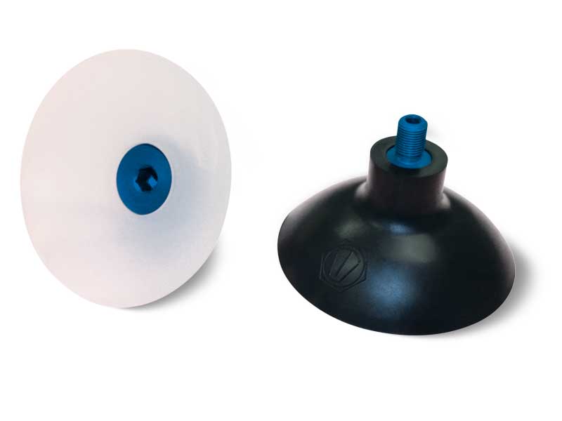
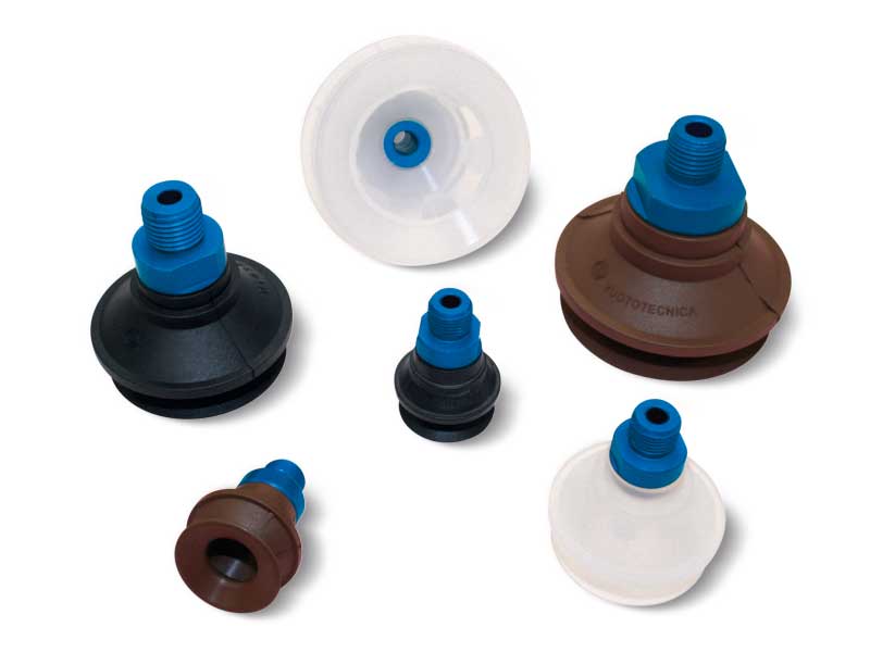
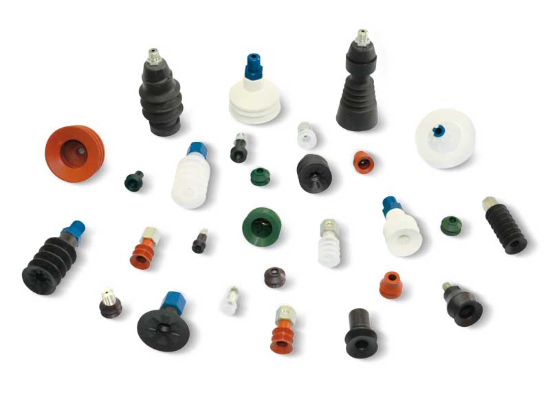
These traditional cup-shaped vacuum cups are suited for gripping and handling objects with flat, slightly concave or convex surfaces.
These widely used vacuum cups have a diameter of 85 mm and are normally available in standard compounds: natural para rubber N, oil-resistant rubber A and silicone S.
They can be cold fitted with no adhesive onto an anodised aluminium support.
The support has been specially shaped to perfectly fit with the vacuum cup and is equipped with a male threaded pin to facilitate fastening to the automation. Moreover, they have a M8 threaded hole for any necessary insertion of a grub screw with calibrated hole (see pg. 1.135), having the function of reducing the quantity of air to be suctioned.
These cups are extremely easy to replace; simply request the cup indicated in the table in the desired compound when requesting the spare part.
Cups in special compounds, listed on top, and supports in different materials can be provided upon specific request in minimum quantities to be defined in the order.
Product codes: 018510 000828 0008136 000891 088510 088512 088513 000829 000846 088525 088526
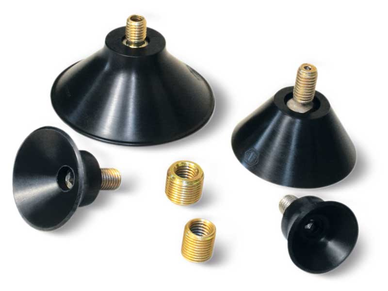
This range of rather sturdy and deep cups is designed to handle bodywork parts and components in moulded steel sheet. These cups are produced with a special compound called BENZ, which can withstand heavy-duty work and the chlorine usually contained in the oil used for moulding and drawing of steel sheets.
The galvanised steel support is vulcanised onto the cup. Galvanised steel adapters are also available in order to modify the suction connection from M10 to gas threading.
Cups in other special compounds, listed on top, can be provided upon request in minimum quantities to be defined in the order.
Product codes: 083038B 084041B 084041N 086045B 0860451/4B 088050B 0008130 0008131
Suction cups for handling plastic films, flow packs and the packaging sector
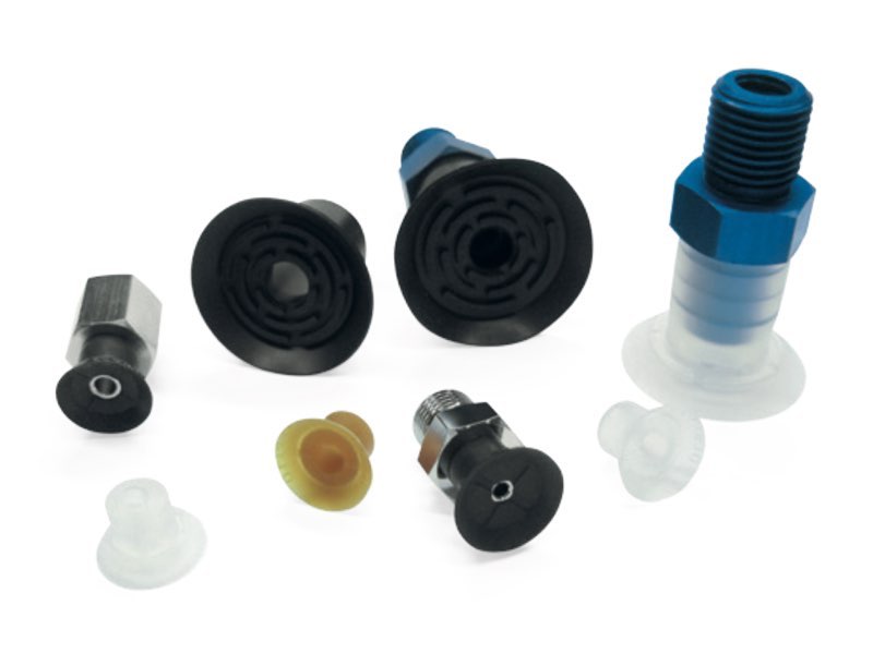
This series of vacuum cups is specifically designed for handling thin, lightweight and delicate objects, such as plastic or paper bags.
The especially thin lip allows the vacuum cup to easily adapt to changes in the shape of the material to be picked up or opened, ensuring effective adhesion even on surfaces that are not perfectly regular.
The internal cleats perform a fundamental function: they distribute the vacuum evenly across the entire surface of the vacuum cup, thus preventing very thin materials from being deformed or sucked directly into the central hole.
To ensure the best performance when gripping plastic or paper products, we recommend using the Para compound, known for its excellent adhesion properties and gentleness on the material being handled.
Product codes: 011409 0008239 0008240 081409 081409F 011410 000803 000804 081410 081410F 011712 000806 000803 081712 081713 011812 000867 000864 081812 081812F 012724 013024 013024L 000815 082724 083024 083024L
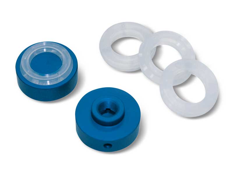
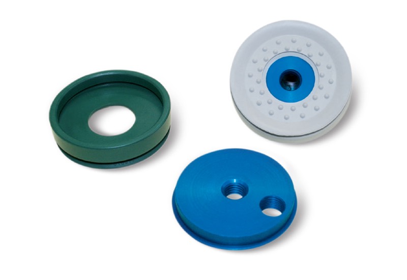
These cups have been designed to meet the need of lifting objects with a central hole.
Their very thin lip allows them to grip very rough surfaces, such as grinding wheels and discs.
They are particularly recommended for handling CDs, perforated discs, toothed wheels, pulleys and other similar objects.
Their supports are made with anodised aluminium and are provided with a threaded hole in the centre to allow suction, as well as its fastening to the automation.
The cups are cold fitted onto them without any adhesives.
To guarantee maximum flexibility, the cups for gripping grinding discs are made with natural para rubber N, while those for handling CDs are made with silicone S. Cups in special compounds, listed on top, can be provided upon request in minimum quantities to be defined in the order.
To replace, simply request the single vacuum cup indicated in the table in the desired compound.
Product code: 012406S 0008232 082406S 013106S 0008231 083106S 014613N 017314N 019514N 000868 000872 000873 084613N 087314N 089514N
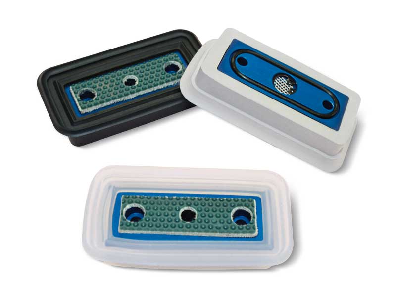
Rectangular flat vacuum cups with anti-slip support
These cups share the same technical and mechanical features with the ones described above, but their support has a special non-slip plastic coating that make them particularly suited for clamping glass and smooth marble.
A built-in stainless steel mesh filter in the suction hole and an O-ring seal at the base of their support are the other special features of these cups.
They are also provided with two or for housings for TCCE screws, according to their size, for fixing them to the work surface.
Product codes: 014075 0008184 084075M1 0112090 0115075 0008256 0008257 0812090M1 0815075M1
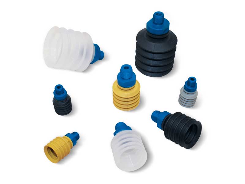
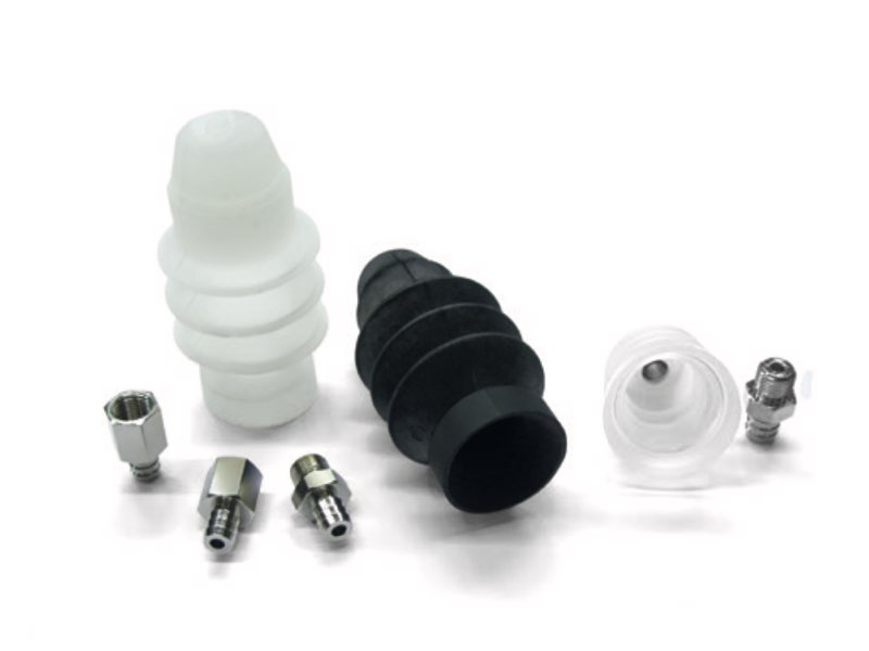
The bellows cups described on these pages have been specially designed for handling baked goods, such as biscuits, bread, pizza, etc., as well as plastic or paper bags containing chocolates, sweets, pasta, flour, powder, etc.
Thanks to their great flexibility, they can also be used to compensate flatness errors or for gripping on inclined surfaces. Their anodised aluminium supports are provided with a threaded male or female central pin to allow suction and to fasten it to the automation.
The vacuum cups can be fitted on them without the aid of adhesives.
To replace, simply request the single vacuum cup indicated in the table in the desired compound.
Product codes: 012023 013032 014042 015053 0008133 0008135 0008142 082023 083032 084042 085053 0008295 0008293 0008279 012023 013032 014042 015053 0008132 0008134 0008141 082023F 083032F 084042F 085053F 0008295 0008293 0008279 0008489
Reinforced bellow vacuum cups with male and female supports
The particular shape of these bellows cups allows them to quickly crumple up when in contact with the surface of the load to be lifted and in presence of a vacuum. This quick movement prevents the load below from remaining stuck to the surfaces or load underneath.
Thanks to this particular feature, these bellows cups are recommended for handling paper and cardboard sheets, thin metal sheets, wooden panels, glass sheets etc.
Thanks to their great flexibility, they can also be used to compensate flatness errors or for gripping on inclined surfaces. Their anodised aluminium supports are provided with a threaded male or female central pin to allow suction and to fasten it to the automation. The vacuum cups can be fitted on them without the aid of adhesives.
To replace, simply request the single vacuum cup indicated in the table in the desired compound.
Product codes: 012219 013426 014328 015335 0008133 0008135 0008142 0008132 0008134 0008141 082219 083426 084328 085335 082219F 083426F 084328F 085335F
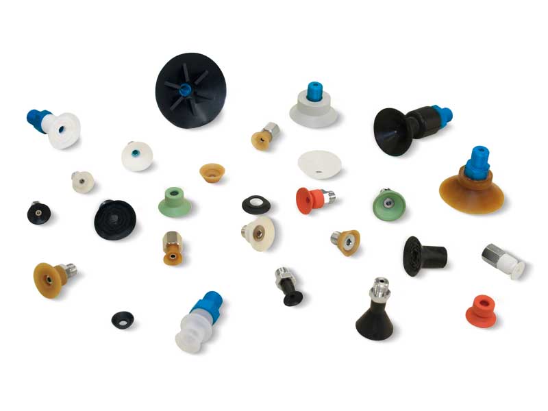
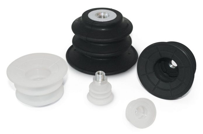
The cups shown on this page and on the next have been designed to solve many of the gripping and handling problems we have encountered in over thirty years of activity. They differ from all the other cups for the variety of their shapes. They are suited for gripping CDs, labels, bags, paper or plastic sheets, stickers, chocolates, cardboard, tiles, small metal objects, plastic objects, etc.
Their nickel-plated brass or anodised aluminium supports are provided with a threaded male or female pin to enable suction and to fasten them to the automation.
These cups can be manually assembled onto their supports with no adhesives, simply by pressing them in. They are provided in standard compounds and, upon request, can be provided in minimum quantities and in other special compounds, listed on top, to be defined in the order.
Product codes: 010713 010807S 011108S 011409 011410 011415 011432 011504N 011515 011626 011712 011812 011931 012004 012006S 012008 012011S 012012 012014N 012015 012024 012206 012224 012245 012299S 012508A 012512 012514N 082522 082527 012528 012610 013112S 013230 013236 013512 014014A 014018 014025 014070N 014430N 014818 015020 015418 016528 080713 080807 081108 081409 081409F 081410 081410F 081415 081415F 081432 081432F 081504 081515 081626 081712 081713 081812 081812F 081931 082004 082006 082008 082011 082012 082012F 082014 082014F 082015 082015F 082024 082024F 082206 082224 082245 082229 082508 082512 012514 082514 082528 082528F 082610 082724 083024 083024L 083112 083230 083236 083512 084014 084018 084024 084070 084430 084818 085020 085418 086528
These bellows cups crumple up when in contact with surface to be gripped and in presence of a vacuum, thus creating a quick lifting movement independently from the automation. This rapid movement prevents the load beneath from remaining stuck to the lifted one. Thanks to their great flexibility, they can also be used to compensate flatness errors or for gripping on inclined surfaces.
The cups shown on this page are the ideal solution for our customers; in fact, they have been designed for handling biscuits, stickers, crackers, sheets, labels, small metal and plastic objects, cardboard, paper and plastic bags, delicate products, chocolate and regular eggs, laminated plastic, etc.
Their nickel-plated brass or anodised aluminium supports are provided with a threaded male or female pin to enable suction and to fasten them to the automation.
These cups can be manually assembled onto their supports without any adhesives, simply by pressing them in. They are provided in standard compounds and, upon request, can be provided in minimum quantities and in other special compounds, listed on top, to be defined in the order.
Product codes: 010509 010650 080650 010850 080850 011150 081150 011116 081116 081117 081117F 011523 081523 081523F 081524F 081526F 011620 081620 081621 081621F 011823 081823 081823F 081824F 081826F 011829 081829 081829F 081830F 081831F 011835S 081835 081835F 081836F 081837F 011850 081850 081851 081852 011917 081917 081918 012060 082060 082061 082062 012535 082535 082540 013050 083050 083050F 013099 083099 083099F 013055 083055 083055F 083240 083241A 083350 014050 084050 084050F 014080 084080 084080F 014290 084290 014290 084290F 015070 085070 015260 085060 015250 085250 015630 085630 017530 087530 017531S 087531S 015060 018060
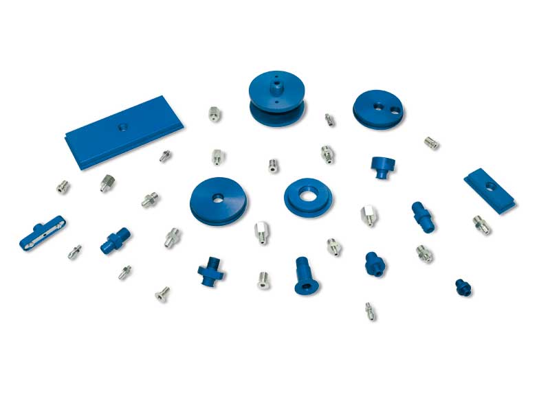
The supports and accessories shown and described on this page and on the following pages are the same as those already described in the previous pages, alongside their respective vacuum cups. On these pages, the customer can also find the list of the vacuum cups for which each support is suited.
They are specially shaped to perfectly adhere to the internal profile of the cups and they are provided with a male or female axial pin in order to allow suction, as well as to fasten them to the automation.
These cups can be manually assembled onto their supports without any adhesives, simply by pressing them in.
They are made with nickel-plated brass or anodised aluminium or with special materials upon request.
Product codes: 000801 000802 000803 000804 000805 000806 000807 000808 000809 000810 000814 000815 000818 000819 000820 000821 000822 000824 000826 000828 000829 000831 000832 0008424 000833 000834 000835 000844 000846 000850 000858 000859 000860 000861 000862 000864 000865 000866 000867 000868 000870 000871 000872 000873 000875 000876 000881 000882 000883 000891 0008892 0008101 0008107 0008109 0008111 0008112 0008113 0008108 0008115 0008116 0008117 0008118 0008119 0008123 0008126 0008127 0008132 0008133 0008134 0008135 0008136 0008141 0008142 0008144 0008145 0008146 0008147 0008148 0008155 0008162 0008163 0008172 0008173 0008184 0008231 0008232 0008233 0008234 0008236 0008237 0008238 0008239 0008240 0008241 0008242 0008243 0008244 0008245 0008246 0008247 0008248 0008249 0008250 0008256 0008257 0008474 0008475 0008280 0008281 0008286 0008287 0008343 00082345 0008405 0008403 0008344 0008346 0008404 0008402 0008373 0008372 0008376 0008375 0008374 0008377 0008394 0008395 0008366 0008364 0008396 0008397 0008392 0008393
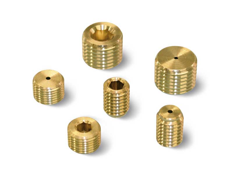
Threaded grub screw with calibrated hole - reductions
These threaded grub screws with calibrated hole are used to reduce the cup suction section, thus reducing vacuum losses in case the cup fails to grip.
They are made of brass and can be inserted in all the cup supports set for this application.
Product codes: 0008122 0008121 0008120 0008164 0008165 0008176 0008334
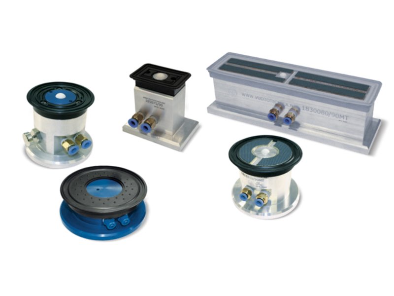
To meet the increasingly demanding requirements of glass processing machine manufacturers, we have developed a line of high-precision suction cups with a guaranteed height tolerance of ±0.05 mm. Standard flat suction cups are available in three different compounds: NBR, Para and Silicone.
The lower perimeter seal is delimited by an O-ring made exclusively of silicone.
All suction cups, both with self-locking support and mechanical clamping, are manufactured to maintain a constant gripping height, allowing them to be used in combination with different shaped and sized models.
Upon request, we also manufacture supports with non-standard heights to adapt to particularly complex or specialised CNC machining operations.
Please refer to the following pages for more details on the technical specifications of models.
For the best choice of clamping system for your application, our Technical Department is available to provide advice and personalised support.
Note: sales may be subject to minimum purchase quantities, depending on the type requested.
Product codes: 050110 050210 050310 050410 016515 056515 018515 0111010 0115010 058515 0511010 0515010 016515 056515M 056565 018515 0111010 058515M 0511010M 018515 0111010 058565 0511065 230110 230115 230210 230510 018515 0111010 0115010 168515 1611010 1615010 014075 0112090 0115075 164075 1612090 1615075 188515 1811010 1815010 014075 0112090 0115075 184075 1812090 1815075 018515M 0111010M 0115010M 0125020 188515/90MT 1811010/90MT 1815010/90MT 1825020/90MT 288515/90MT 2811010/90MT 2815010/90MT 2825020/90MT 014075 0112090 0115075 0130080 01300150 184075/90MT 1812090/90MT 1815075/90MT 1830080/90MT 18300150/90MT 284075/90MT 2812090/90MT 2815075/90MT 2830080/90MT 28300150/90MT 0111010M 0115010M 0125020 1811010/160MT 1815010/160MT 1825020/160MT 2811010/160MT 2815010/160MT 2825020/160MT 0112090 0115075 0130080 01300150 1812090/160MT 1815075/160MT 1830080/160MT 18300150/160MT 2812090/160MT 2815075/160MT 2830080/160MT 28300150/160MT 086511A 186511/90A 085075A 185075/90A 218511/90A 0815011A 2115011/90A 0111010M 0115010M 2111010 2115010 014075 214075PL 214075/84PL 214075PP 214075/84PP 0112090 0115075 2112090 2115075 2115075/84
The bellows vacuum cups illustrated on this page and on the next have been specially designed to adapt to the shape of eggs.
The thin lip ensures maximum adaptability and a delicate grip on eggs, minimising the risk of cracks or breakage. The bellows compensate for differences in height or position of the eggs and ensure stability during handling, preventing damage.
They are available in Silicone or Para, which guarantee excellent adhesion even on smooth surfaces. They are widely used in automatic and semi-automatic packaging lines thanks to their reliability.
Product codes: 013550 014080 014290N
These cups have been designed in particular for handling metal sheets, glass, wooden panels, machined marble and granite and other similar materials.
The shape of their lips allows a firm grip of the surface of the load to be handled, eliminating any oscillation and significantly reducing the air volume contained within, thus allowing quicker grip and release. These cups are provided with cleats which, besides avoiding the load to bend in correspondence of the gripping point, also have the purpose of increasing the friction surface with the vertically lifted load, preventing it from slipping.
They are normally available in the three standard compounds but can be supplied in special compounds listed on top and in a minimum amount to be defined in the order, upon request. These cups can be cold fitted with no adhesives onto their anodised aluminium support equipped with a threaded hole in the centre to allow its fastening to the automation and, upon request, can be supplied with a side hole with gas threading for the suction fitting.
These cups are extremely easy to replace; simply request the cup indicated in the table in the desired compound when requesting the spare part.
Product codes: 016515 016516 000832 0008424 000236 000613 086515 0865151/4 086516 086517 018515 018516 000832 0008234 0008424 008233 000236 000613 088515 0885151/2 0885151/4 0885153/4 088516 088517 0111010 000833 000237 000614 0008123 0811010 0811011 0811012 0811013 0115010 000835 0008107 0008119 0008145 000615 0815010 0815012 0815013 0815014 0815016
Vacuum cups with two bellows for heavy-duty packaging
Specifically designed vacuum cups for tripping and handling particularly heavy boxes and cardboard packaging in general.
Their thick, sturdy lip absorbs tears and sudden accelerations, typical of robotised movements. The double bellows enables improved adaptability to the gripping surface, even if not perfectly perpendicular to the axis of the vacuum cup, and can recover evident unevenness of the loads to be lifted.
The supports, all made of anodised aluminium, are equipped with a male or female central threaded pin to allow suctioning and clamping to the automation. The vacuum cups can be fitted on them without the aid of adhesives.
To replace, simply request the single vacuum cup indicated in the table in the desired compound.
Product codes: 013527 015240 0008394 0008395 0008366 0008364 0835271/8 0852401/8 083527 085240 013527 015240 0008396 0008397 0008392 0008393 0835271/8F 0852401/8F 083527F 085240F 087543SR 0811073SR 0008373 0008372 0008376 0008375 087543M 0875433/8M 0811073M 08110731/2M 087543SR 0811073SR 0008374 0008377 0875433/8 08110731/2
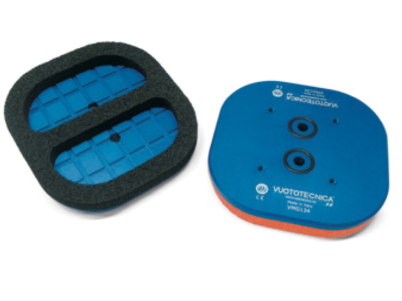
The VMG134 vacuum cup is specifically designed for use on automatic sorting machines dedicated to handling textured tiles. Its shape and the material used allow for a secure grip even on uneven, rough or raised surfaces, where traditional vacuum cups are not effective.
Made of high-density foam rubber, the VMG134 maintains its elasticity even after numerous work cycles, ensuring consistent performance over time. It is available in three different compounds, each suitable for specific thermal conditions: the EPDM rubber (SB) version is resistant to temperatures between -40 °C and +130 °C, the Geranium foam rubber (OF) works between -40 °C and +80 °C, while the neoprene (NF) is suitable for temperatures between -20 °C and +80 °C.
One side of the vacuum cup is self-adhesive, allowing for quick and secure attachment to the support. The vacuum cup support is made of anodised Anticorodal, a material that ensures strength
and corrosion resistance.
It has four holes for attachment to the automatic machine and two vacuum connections, which allow for gripping and even partial movement of the piece.
Both connections are sealed with NBR O-rings, ensuring optimal system sealing.
For maintenance, simply replace the self-adhesive foam rubber only, requesting it in the desired compound based on operating conditions. The VMG134 vacuum cup is therefore an effective, durable and versatile solution for all applications where the surface of the material to be handled does not allow the use of conventional vacuum cups.
Product codes: 01134134 VMG134 0008479
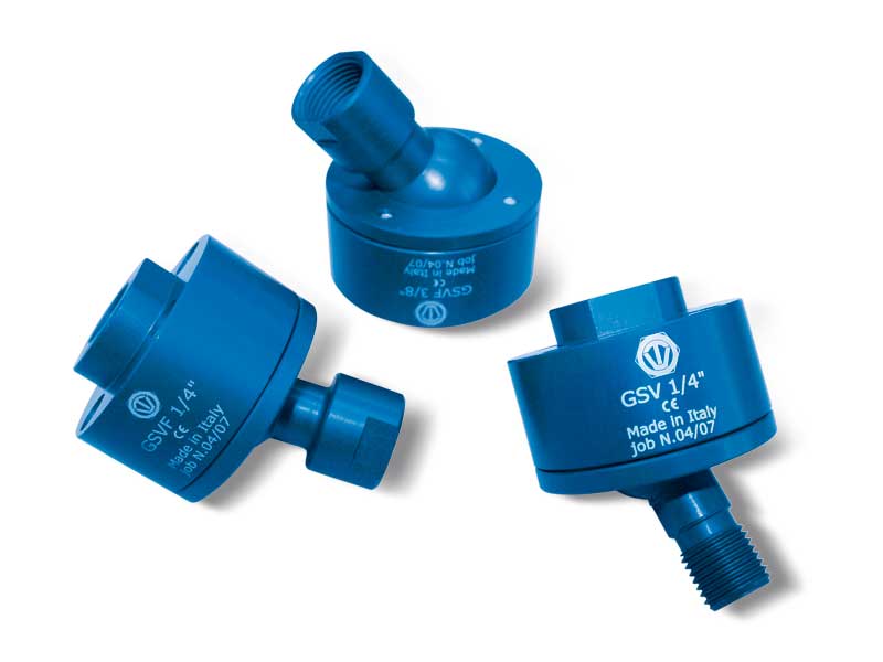
Positionable ball joint couplings with axial vacuum connection
The positionable ball joints couplings in anodised aluminium allow the installed vacuum cups to be rotated 360° and to be tilted by up to 35° in order to properly position them with respect to the gripping surface on the object to be handled, while at the same time ensuring a perfect grip and proper suction through the joint itself.
Product codes: GSV1/8 GSV1/4 GSV3/8 GSVF1/8 GSVF1/4 GSVF3/8
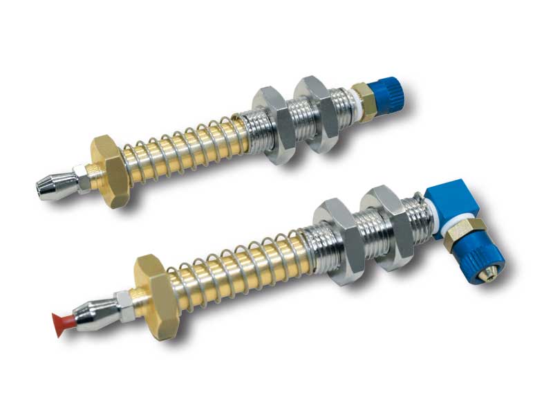
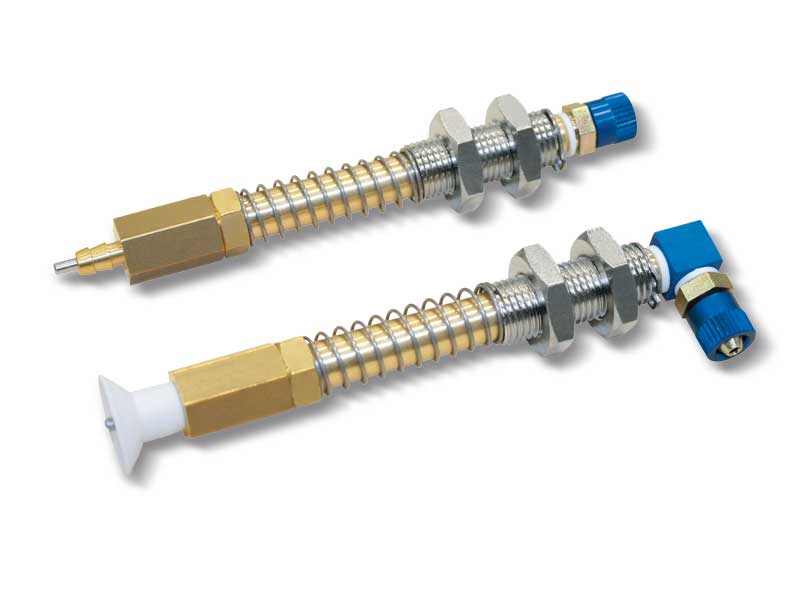
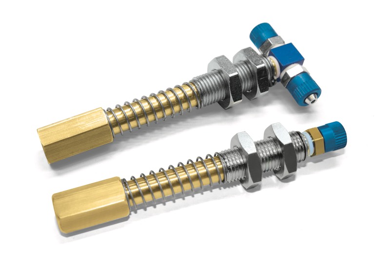
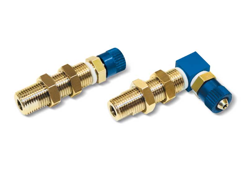
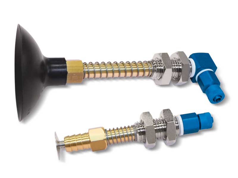
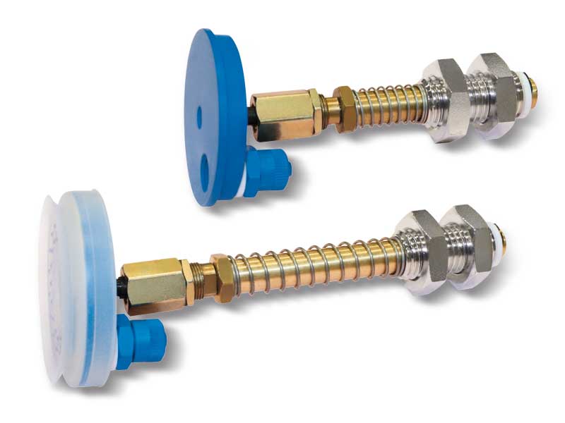
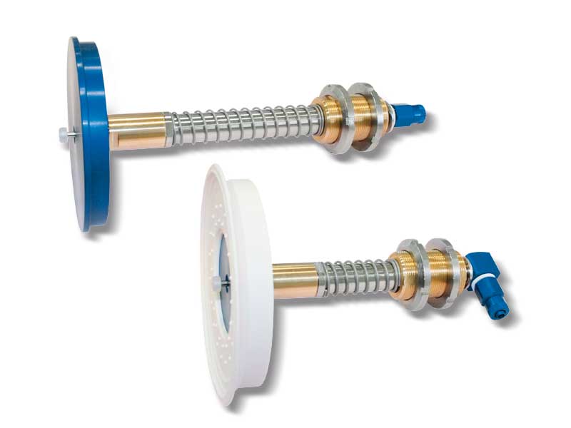
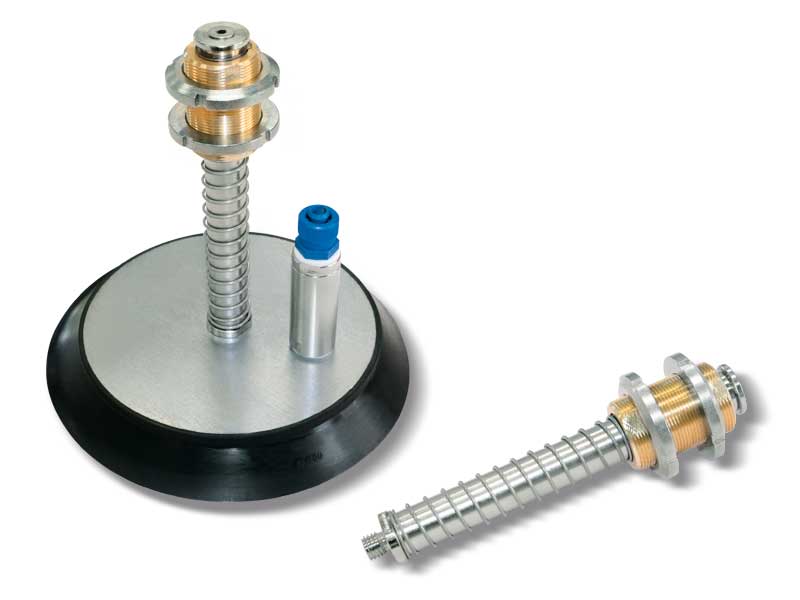
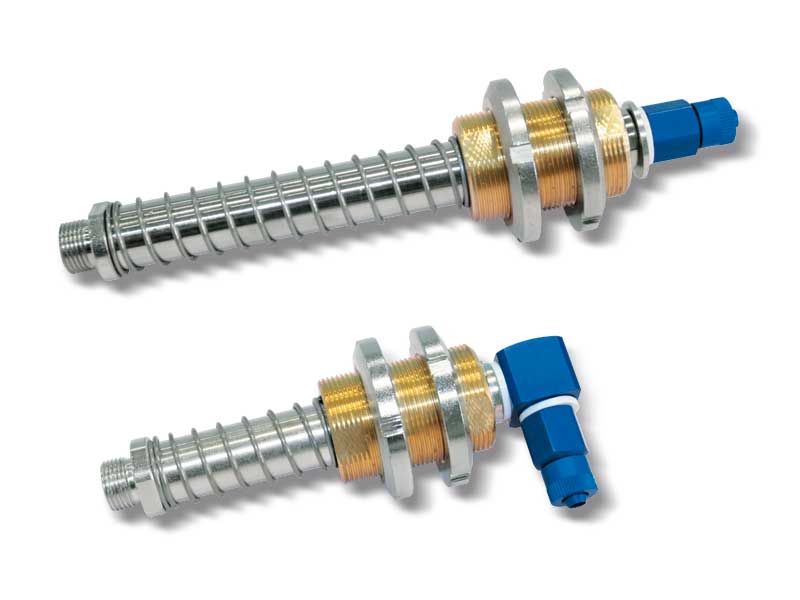
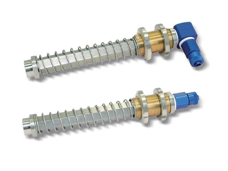
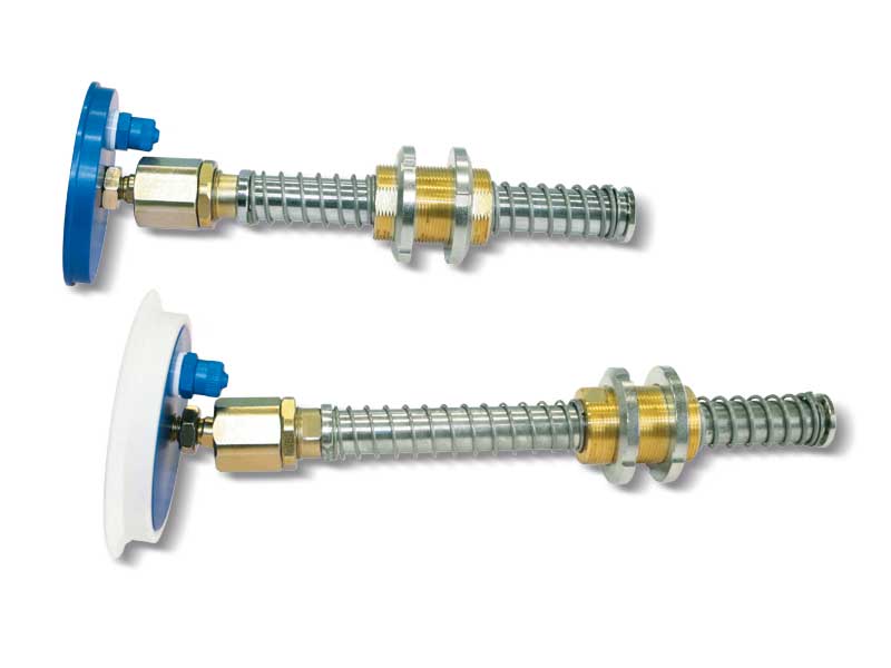
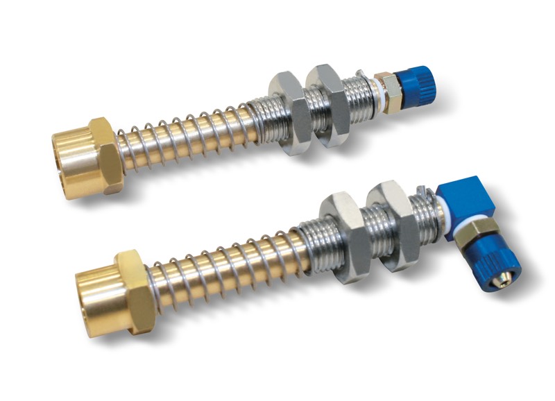
The main feature of the cup holders described on these pages is their reduced size, which results in a reduced weight and bulk. They allow use of even very small cups, guaranteeing, given the same diameter, the same performance as the larger series.
They are composed of:
- A brass stem for fastening the cup
- A threaded sleeve equipped with nuts, for mounting the vacuum up holder on the automation
- A spring to cushion the impact of the cup and to, at the same time, keep pressure with the load to be lifted
- A quick coupling for connection with the suction hose.
Product codes: 200430 200830 201030 201415 202515 203515 202530 202535 204530 205020 200650 201523 201850 201917 202023 203032 200735 203050
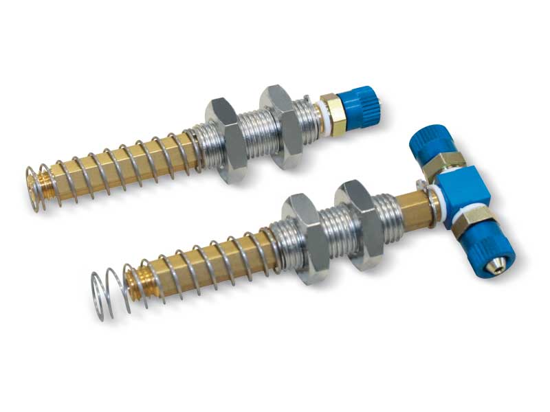
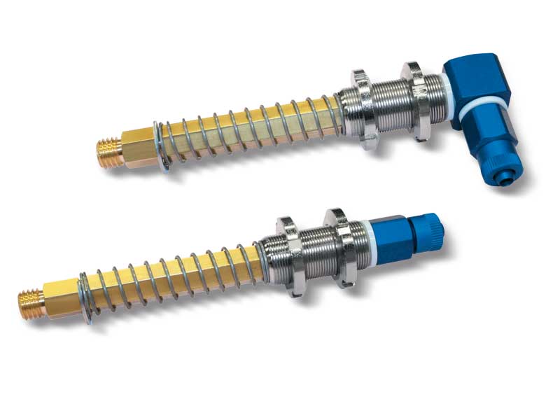
The vacuum cup holders shown on this page have a shorter stroke and their special design that allow for further bulk and weight reduction in the overall dimensions and weight of these vacuum cups compared to normal mini vacuum cup holders. They are composed of:
- A brass stem for fastening the cup;
- A threaded sleeve equipped with nuts, for mounting the vacuum up holder on the automation;
- A spring to cushion the impact of the cup and to, at the same time, maintain constant pressure with the load to be lifted;
- A quick coupling for connection with the suction hose, consisting of one small hose connector as standard or two on request, radial They are particularly suited for small cups to be manually assembled with diameters ranging between 10 and 30 mm.
Product codes: 200535 201010 202510 201138
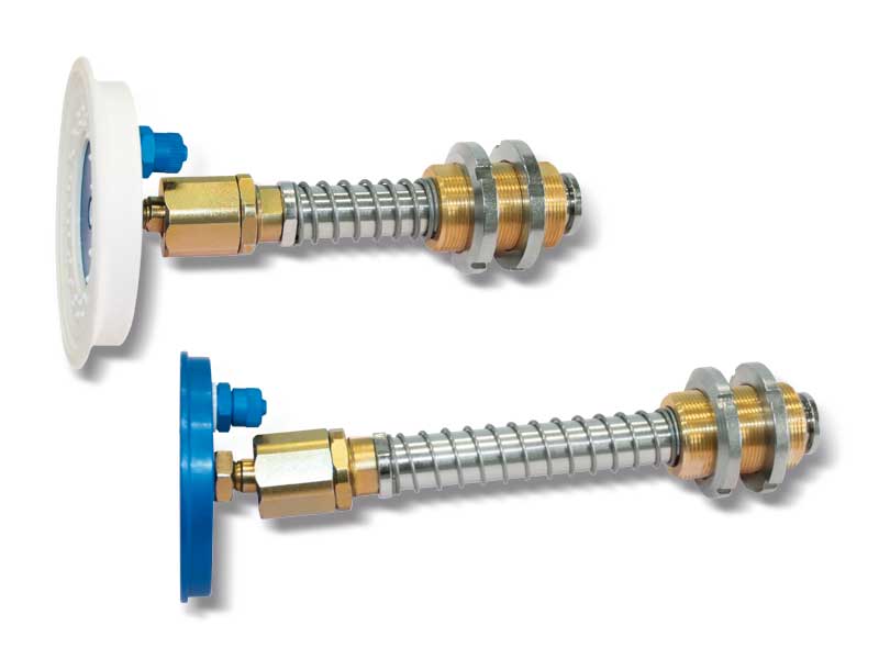
They share the same mechanical features at the other mini vacuum cup holders.
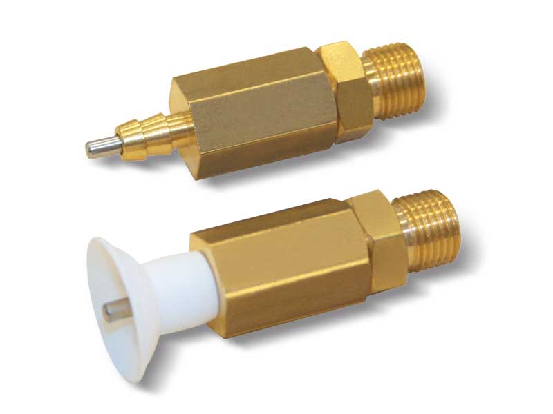
Their distinctive feature is the plunger valve solidly connected to a conical spear valve, which activates suction, and therefore creates vacuum, only when the cup comes into contact with the load to be lifted.
They are composed of:
- A brass stem for fastening the cup;
- A threaded sleeve equipped with nuts, for mounting the vacuum up holder on the automation;
- A spring to cushion the impact of the cup and to, at the same time, maintain constant pressure with the load to be lifted;
- A quick coupling for connection with the suction hose;
- A solidly connected plunger valve with a conical shutter.
Product codes: 201260 201560 201860 202060 202260 202560 203060 203560 204060
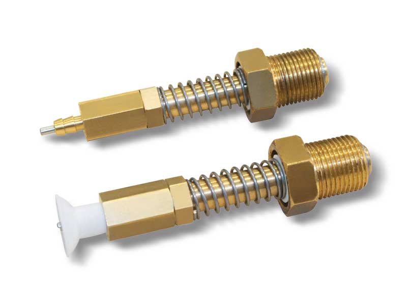
Mini vacuum cup holders with plunger valve and built-in bush
The vacuum cup holders shown on this page and the following pages are characterised by their very compact size. They feature a hexagonal threaded bush, which allows them to be assembled directly to the vacuum manifold, with considerable savings in terms of pipes and fittings.
They are composed of:
- A brass stem for fastening the cup;
- A spring to cushion the impact of the cup and to, at the same time, maintain constant pressure with the load to be lifted;
- A quick coupling for connection with the suction hose;
- A plunger valve solidly connected to a conical spear valve, which activates suction and therefore creates a vacuum, only when the cup is in contact with the load to be lifted;
- The hexagonal threaded bush for cup holder assembly with the vacuum manifold is equipped with a seal and has the task of driving and holding the brass stem for fixing the vacuum cup.
Product codes: 201265 202565 203565
Mini vacuum cup holders with plunger valve with no springing
They have the same function as the mini vacuum cup holders with plunger valve but, for further bulk reduction, the cushioning spring, the threaded pipe with nuts for fixing to the automation and the quick coupler have been removed.
This type of cup holder is to be directly assembled to the vacuum manifold. To allow quick assembly, its end is provided with a threaded male shank.
They are composed of:
- A brass stem for fastening the cup;
- A plunger valve solidly connected to a conical spear valve, which activates suction and therefore creates a vacuum, only when the cup is in contact with the load to be lifted.
Product codes: 201261 202561 203561
Mini vacuum cup holders with built-in shut-off valve
In addition to having all the other features of the mini vacuum cup holders, these also have a built-in shut-off valve. The function of the shut-off valve
is to automatically close suction when the cup is not in contact with the surface of the load to be handled or in case of a faulty grip or of considerable transpiration, thus preventing the reduction of the level of vacuum on
the remaining cups of the system that are regularly gripping a load. The advantage of this is that the placement or the exclusion of the non-gripping cups is no longer binding. Vacuum cups with a minimum diameter of 10 mm and maximum diameter of 50 mm can be assembled on these cup holders, provided they have a 1/8 “male threaded gas support.
They are composed of:
- A brass stem for fastening the cup;
- A threaded sleeve equipped with nuts, for mounting the vacuum up holder on the automation;
- A spring to cushion the impact of the cup and to, at the same time, maintain constant pressure with the load to be lifted;
- A quick coupling for connection with the suction hose;
- A shut-off valve.
Product codes: 209935
The technical features are the same as for the mini vacuum cup holders, with their distinctive features being their brass stem with hexagonal cross-section and the steel drive bushwith hexagonal hole. This prevents the stem from rotating on its axis, and, as a result, also the cup and its support from rotating. They are suited for cups with male or female support with diameters ranging from 10 mm to 60 mm, but they have been specially designed for the installation of rectangular, concave and elliptical cups.
They are composed of:
- A brass stem with a hexagonal cross-section;
- A threaded sleeve equipped with nuts, for mounting the vacuum up holder on the automation;
- A spring to cushion the impact of the cup and to, at the same time, maintain constant pressure with the load to be lifted;
- A quick coupling for connection with the suction hose.
Product codes: 209508 209528 209538
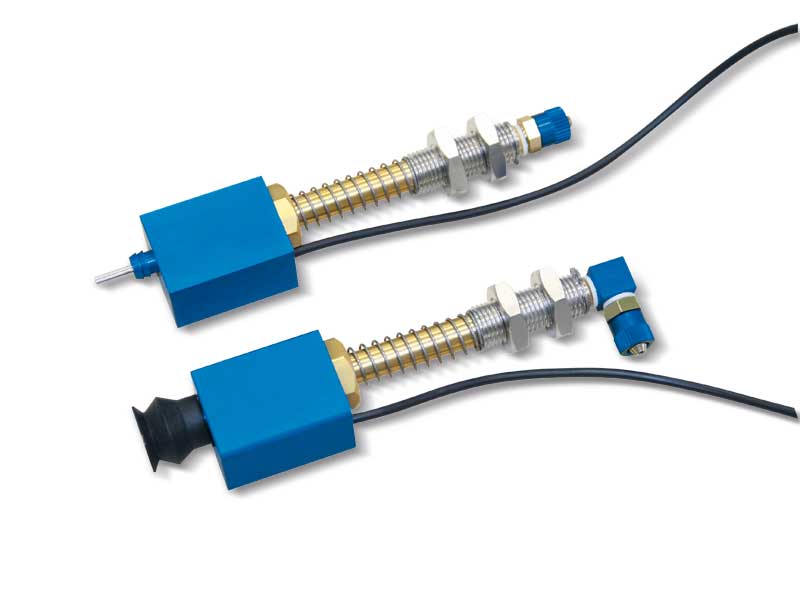
These cup holders share the same technical features at the other mini vacuum cup holders.
They are equipped with a magnetic sensor built into the cup holders to provide an electric signal to the machine every time the vacuum cup performs gripping.
This is the reason why they are recommended to be used on piece counter handlers, boxing machines and in all those cases in which the presence of the gripped object is to be guaranteed. These cup holders have been designed for gripping chocolate, snacks, croissants and similar products and they are currently made in the version represented on this page.
They are composed of:
- A brass stem for fastening the cup;
- A threaded sleeve equipped with nuts, for mounting the vacuum up holder on the automation;
- A spring to cushion the impact of the cup and to, at the same time, maintain constant pressure with the load to be lifted;
- A quick coupling for connection with the suction hose;
- A magnetic sensor equipped with a 3-metre connection cable;
- An anodised aluminium body to protect the magnetic sensor.
Product codes: 209902 209903
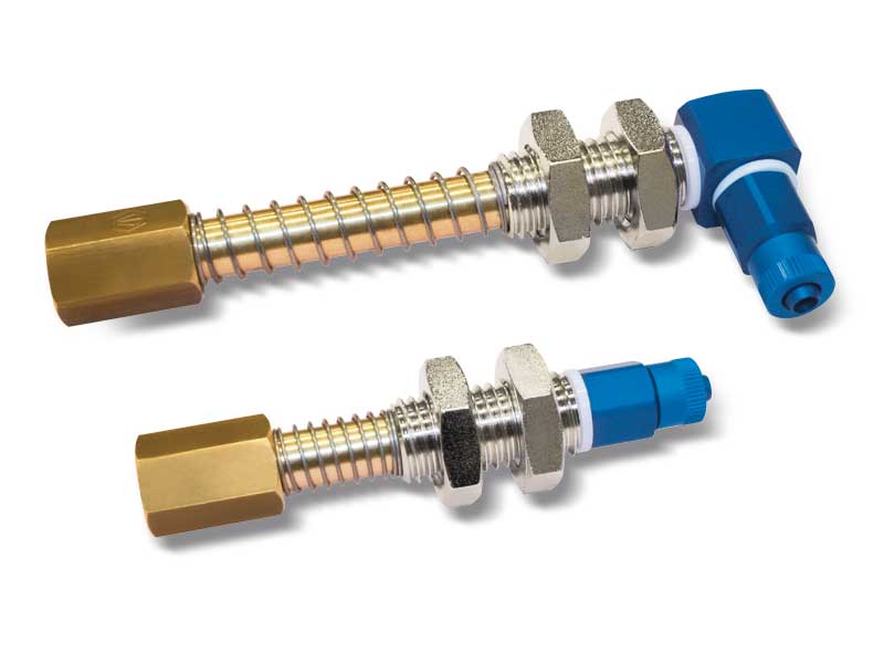
Fix vacuum cup holders have been designed to adjust the height of the vacuum cups with support thanks to the threading along the entire length of the threaded bush. The ends are female threaded for mounting the vacuum cup with support and the connector.
They are composed of:
- A threaded bush equipped with nuts, for mounting the vacuum up holder on the automation;
- A quick coupling for connection with the suction hose.
Product codes: 207001 207005
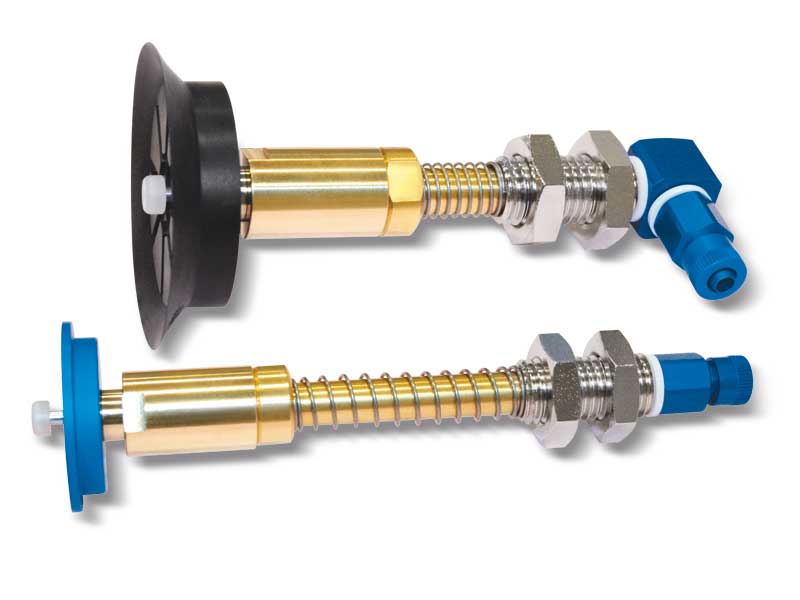
These basic cup holders are built in a simple and rational way, guaranteeing maximum sturdiness and duration. They are composed of:
- A brass stem for fastening the cup;
- A nickel-plated steel threaded sleeve equipped with anti-friction bushes for quick assembly of the cup to the automation;
- A spring to cushion the impact of the cup and to, at the same time, maintain constant pressure with the load to be lifted;
- A quick coupling for connection with the suction hose.
Product codes: 022510 022515 022724 023515 024510 024515 025020 021228 021265 011295 026515 027624 028020 028510 0211010 0211015 022023 023032 023050 021028M 021065M 021095M 021228M 021265M 011295M 025250 025335 025630
They share the same mechanical features as basic vacuum cup holders. Their distinctive feature is the plunger valve solidly connected to a conical spear valve, which activates suction, and therefore creates vacuum, only when the cup comes into contact with the load to be lifted.
They are composed of:
- A brass stem for fastening the cup;
- A nickel-plated steel threaded sleeve equipped with anti-friction bushes for quick assembly of the cup to the automation;
- A spring to cushion the impact of the cup and to, at the same time, maintain constant pressure with the load to be lifted;
- A quick coupling for connection with the suction hose;
- A solidly connected plunger valve with a conical shutter.
Product codes: 034510 036010 036515 038020 038510 038515 0311010
Basic vacuum cup holders with built-in shut-off valve
Along with all the other features they share with the other basic vacuum cup holders, , these have a built-in shut-off valve. The function of the shut-off valve is to automatically close suction when the cup is not in contact with the surface of the load to be handled or in case of a faulty grip or of considerable transpiration, thus preventing the reduction of the level of vacuum on the remaining cups of the system that are regularly gripping a load. The advantage of this is that the placement or the exclusion of the non-gripping cups is no longer binding. Vacuum cups with a minimum diameter of 10 mm and maximum diameter of 50 mm can be assembled on these cup holders, provided they have a 1/8" male threaded gas support.
They are composed of:
- A brass stem for fastening the cup;
- A nickel-plated steel threaded sleeve equipped with anti-friction bushes for quick assembly of the cup to the automation;
- A spring to cushion the impact of the cup and to, at the same time, maintain constant pressure with the load to be lifted;
- A quick coupling for connection with the suction hose;
- A shut-off valve.
Product codes: 029928 029965 029995
The technical and mechanical features are the same as for the basic vacuum cup holders. Their distinctive feature is their articulated joint in hardened steel, which allows the flat cups installed on these cup holders to adapt themselves to the loads to be lifted with slightly tilted surfaces, as well as to compensate possible verticality errors that can arise between the cup holder and the automation fixing support.
They are composed of:
- A brass stem for fastening the cup;
- A nickel-plated steel threaded sleeve equipped with anti-friction bushes for quick assembly of the cup to the automation;
- A spring to cushion the impact of the cup and to, at the same time, maintain constant pressure with the load to be lifted;
- A quick coupling for connection with the suction hose;
- An articulated joint in galvanised steel.
Product codes: 026520 028520 0211020 0211022
The technical features are the same as for the basic vacuum cup holders, with their distinctive features being their brass stem with hexagonal section and the steel drive bush with hexagonal hole. This prevents the stem from rotating on its axis, and, as a result, also the cup and its support from rotating.
They are suited for cups with male or female support with diameters ranging from 45 mm to 110 mm, but they have been specially designed for the installation of rectangular, concave and elliptical cups.They are composed of:
- A brass stem with a hexagonal cross-section;
- An externally threaded sleeve with an internal hexagonal cross-section, equipped with ring nuts for mounting the vacuum cup holder to the automation;
- A spring to cushion the impact of the cup and to, at the same time, maintain constant pressure with the load to be lifted;
- A quick coupling for connection with the suction hose.
Product codes: 029528 029565 029595 0295281/4 0295651/4 0295951/4
Fix vacuum cup holders have been designed to adjust the height of the vacuum cups with support thanks to the threading along the entire length of the threaded bush. The ends are female threaded for mounting the vacuum cup with support and the connector. They are composed of:
- A threaded bush equipped with nuts, for mounting the vacuum up holder on the automation;
- A quick coupling for connection with the suction hose.
Product codes: 029101 029105 029106
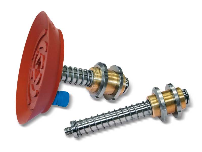
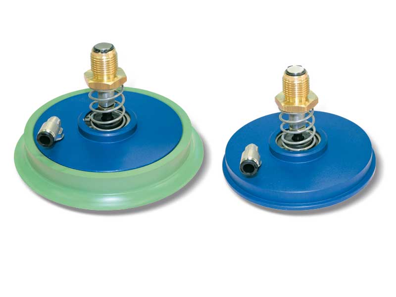
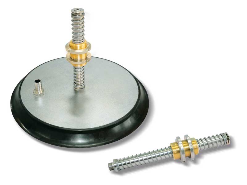
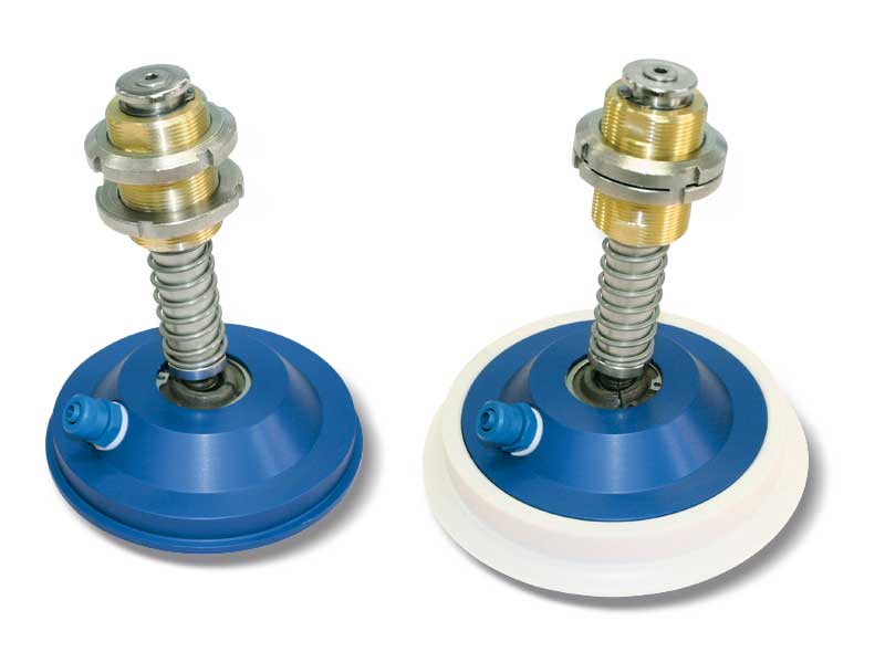
These special vacuum cup holders have been designed to lift and handle heavy loads and to withstand heavy-duty and continuous workloads in dusty or damp environments.
They are composed of:
- A nickel-plated steel stem for fastening the vacuum cup;
- A threaded brass bush, equipped with two anti-friction; bushings, fitted with two ring nuts for fastening the vacuum cup holder to the automation;
- A spring to cushion the impact of the cup with the load to be lifted;
- A safety washer;
- A quick coupling for connection with the suction hose.
Product codes: 068510 068515 069024 0610040 0611010 0611015 0611024 0615010 0615036 0615015 0620010 0625010 0622010OF 0622010NF 0622010A 0630010 0635010 067542 0611030 0611058 0615074 0625030
They share the same mechanical features as basic vacuum cup holders. Their distinctive feature is the plunger valve solidly connected to a conical spear valve, which activates suction, and therefore creates vacuum, only when the cup comes into contact with the load to be lifted.
With these cup holders, it is no longer necessary to install cocks on the suction hoses; for this reason, they are recommended in all those cases in which there is a chance that not all the cups come into contact with the load to be lifted (because of an uneven or incomplete load).
They are composed of:
- A nickel-plated steel stem for fastening the vacuum cup;
- A threaded brass bush, equipped with two anti-friction bushings, fitted with two ring nuts for fastening the vacuum cup holder to the automation;
- A spring to cushion the impact of the cup with the load to be lifted;
- A safety washer;
- A quick coupling for connection with the suction hose;
- A solidly connected plunger valve with a conical shutte.
Product codes: 068520 068522 0611020 0611022 0615020
They share the same technical and mechanical features at the special vacuum cup holders. Their distinctive feature is the push valve on the cup support, which activates suction, and therefore creates vacuum, only when the cup is in contact with the load to be lifted.
With these cup holders, it is no longer necessary to install cocks on the suction hoses; for this reason, they are recommended in all those cases in which there is a chance that not all the cups come into contact with the load to be lifted (because of an uneven or incomplete load).
The same push valve can also be applied with no modification to the special articulated cup holders. They are composed of:
- A nickel-plated steel stem for fastening the vacuum cup;
- A threaded brass bush, equipped with two anti-friction bushings, fitted with two ring nuts for fastening the vacuum cup holder to the automation;
- A spring to cushion the impact of the cup with the load to be lifted;
- A safety washer;
- A quick coupling for connection with the suction hose;
- A plunger valve.
Product codes: 0615022 0630020 0635020
Special vacuum cup holders with built-in shut-off valve
Along with all the other features they share with the other special vacuum cup holders, , these have a built-in shut-off valve. The purpose of the shut-off valve is to automatically close suction when the cup is not in contact with the surface of the load to be handled or in case of a faulty grip or of considerable transpiration.
This thus prevents the reduction of the level of vacuum on the remaining cups of the system which are regularly handling the load. The clear advantage of this system is that the positioning or the exclusion of the non-gripping cups are no longer binding.
Cups with diameters between 85 mm and 150 mm can be assembled onto these cup holders, as long as they are provided with a threaded 3/8” gas female support.
They are composed of:
- A nickel-plated steel stem for fastening the vacuum cup;
- A threaded brass bush, equipped with two anti-friction bushings, fitted with two ring nuts for fastening the vacuum cup holder to the automation;
- A spring to cushion the impact of the cup with the load to be lifted;
- A safety washer;
- A quick coupling for connection with the suction hose;
- A shut-off valve.
Product codes: 069955 0699110
The distinctive feature of these cup holders is their articulated joint in hardened steel, which allows the flat cups installed on these cup holders to adapt themselves to the loads to be lifted even if not completely parallel with the cup plane, as well as to compensate possible verticality errors that can arise between the cup holder and the automation fixing support. Their technical and mechanical features are the same as the other previously described special vacuum cup holders.
They are composed of:
- A nickel-plated steel stem for fastening the vacuum cup;
- A threaded brass bush, equipped with two anti-friction bushings, fitted with two ring nuts for fastening the vacuum cup holder to the automation;
- A spring to cushion the impact of the cup with the load to be lifted;
- A safety washer;
- A quick coupling for connection with the suction hose;
- An articulated joint in galvanised steel.
Product codes: 0611012 0611017 0615012 0615017 0620012 0625012 0622012OF 0622012NF 0622012A 0630012 0635012
Special articulated vacuum cup holders with compact stroke
Marble and glass slabs are handled using vacuum cups that move them between horizontal and vertical positions. To reduce the lever arm and slippage during rotation, special articulated vacuum cup holders with reduced springing have been developed.
These retain the same technical characteristics as the previous models, but with much smaller dimensions thanks to the integration of the articulated joint in the vacuum cup support, the reduction of the steel stem and the modification of the brass bush in order to allow it to be screwed directly onto the automation. Finally, a non-slip plastic coating attached to the support prevents the lifted load from slipping.
They are composed of:
- A steel stem with a spherical part;
- A threaded brass bush for fastening the vacuum cup holder to the automation;
- A spring to cushion the impact of the cup and to, at the same time,
maintain constant pressure with the load to be lifted;
- A 90° swivel quick coupling for connection with the suction hose; - An aluminium support for mounting the vacuum cup, equipped with a spherical seat and vacuum connection;
- Non-slip plastic coating.
Product codes: 0611042 0612742 0615042
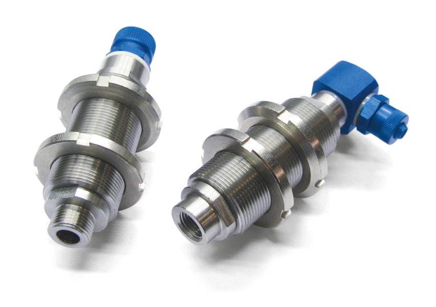
Special stainless steel anti-rotation vacuum cup holders
Designed for the robot-automotive sector, these cup holders offer ideal solutions to various handling problems that arise in all industrial sectors.
In addition the characteristics of the previously described special vacuum cup holders, their distinctive features are their brass stem with hexagonal cross- section and the steel drive bush, also with hexagonal hole. This structure prevents the stem and, as a result, the cup assembled onto it from rotating on its axis.
The drive bush is equipped with two fine thread ring nuts to guarantee an accurate fastening of the cup holder to the automation. Moreover, the two ends of the stem, also in stainless steel, are threaded male or female and interchangeable. The straight quick coupler for the connection to the suction hose is screwed to one end, while the cup with support is assembled onto the other end.
They are suited for cups with a diameter between 40 mm and 200 mm, although they are especially useful for the assembly of rectangular or elliptical vacuum cups.
They are composed of:
- A stainless steel stem with hexagonal cross-section;
- A threaded brass bush with an internal hexagonal cross-section, fitted with two ring nuts for fastening the vacuum cup holder to the automation;
- A spring to cushion the impact of the cup and to, at the same time, maintain constant pressure with the load to be lifted;
- A quick coupling for connection with the suction hose.
Product codes: 065580 065581 065582 0611080 0611081 0611082 065590 065591 065592 065593 065594 065595 065596 0611090 0611091 0611092 0611093 0611094 0611095 0611096
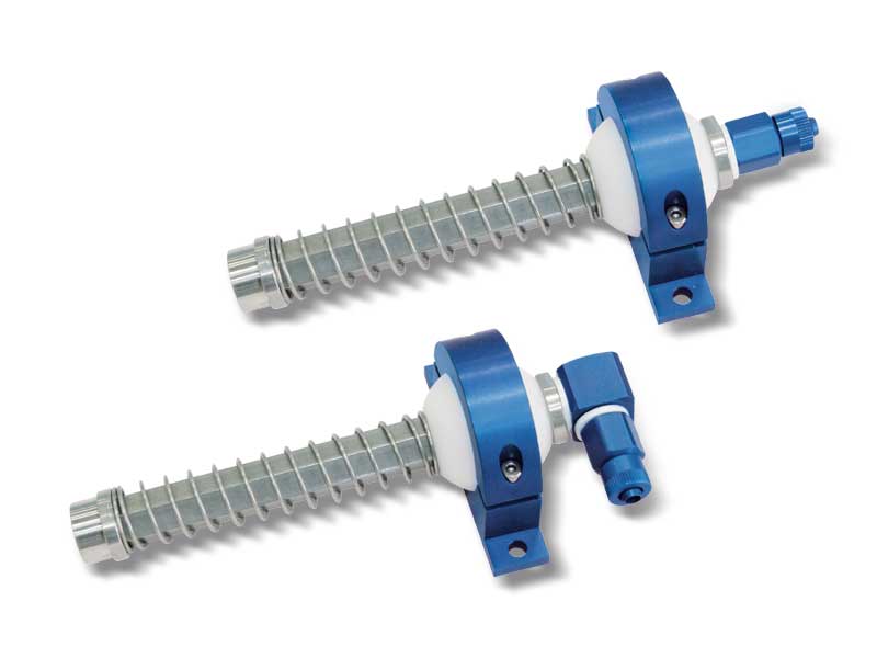
Special anti-rotation vacuum cup holders with spherical swivel support
In addition the characteristics of the previously described special anti-rotation vacuum cups, these cup holders are provided with a nylon spherical swivel support which allows to place and keep the cup in the desired place.
Their fixing support is made with aluminium and is composed of two parts that, screwed together, allow to block the spherical joint, thus keeping the vacuum cup holder in place.
They are suited for cups with a diameter between 40 mm and 200 mm, although they are especially useful for the assembly of rectangular or elliptical vacuum cups.
They are composed of:
- A stainless steel stem with hexagonal cross-section;
- An adjustable nylon ball joint with an internal hexagonal cross-section; - An aluminium support for fastening to the automation;
- A spring to cushion the impact of the cup and to, at the same time, maintain constant pressure with the load to be lifted;
- A quick coupling for connection with the suction hose.
Product codes: 0655100 0655101 0655102 06110100 06110101 06110102 0655110 0655111 0655112 0655113 0655114 0655115 0655116 06110110 06110111 06110112 06110113 06110114 06110115 06110116
All the special vacuum cup holders previously described can also be provided in the double springing version. In this configuration, the cup holder fixing bush is located between two springs: the lower one cushions the impact of the cup with the load to be lifted during the approach phase, while the upper one absorbs the impact of the bush with the cup holder end and ensures gradual loading of the vacuum cup during the lifting phase. The use of this solution is especially recommended when the load to be handled is very heavy, rough or not perfectly flat.
They are composed of:
- A nickel-plated steel stem for fastening the vacuum cup;
- A threaded brass bush, equipped with two anti-friction bushings, fitted with two ring nuts for fastening the vacuum cup holder to the automation;
- Two springs designed to reduce and distribute impact: one serves to cushion the impact of the vacuum cup with the load to be lifted, the other to cushion the impact of the bush against the end of the vacuum cup holder;
- A safety washer;
- A quick coupling for connection with the suction hose.
Product codes: 068513 068517 0611013 0611016 0615013 0615018 0620013 0625013 0622013OF 0622013NF 0622013A 0630013 0635013
Special articulated vacuum cup holders with double springing
The distinctive feature of these cup holders is their articulated joint in hardened steel, which allows the flat cups installed on these cup holders to adapt themselves to the loads to be lifted even if not completely parallel with the cup plane, as well as to compensate possible verticality errors that can arise between the cup holder and the automation fixing support.
The cup holder fixing bush is located between two springs: the lower one cushions the impact of the cup with the load to be lifted during the approach phase, while the upper one cushions the impact of the bush with the cup holder end and gradually loads the cup during the lifting phase.
These cup holders are especially recommended when the load to be lifted is very heavy, rough or not perfectly flat.
They are composed of:
- A nickel-plated steel stem for fastening the vacuum cup;
- A threaded brass bush, equipped with two anti-friction bushings, fitted with two ring nuts for fastening the vacuum cup holder to the automation;
- Two springs designed to reduce and distribute impact: one serves to cushion the impact of the vacuum cup with the load to be lifted, the other to cushion the impact of the bush against the end of the vacuum cup holder;
- A safety washer;
- A quick coupling for connection with the suction hose;
- An articulated joint in galvanised steel.
Product codes: 0611014 0611018 0615014 0615019 0620014 0625014 0622014OF 0622014NF 0622014A 0630014
These special articulated vacuum cup holders have an articulated joint housed in the cup support. This has allowed a reduction of the overall dimensions without affecting performance.
They are composed of:
- A nickel-plated steel stem with articulated joint
- A threaded brass bush, equipped with two anti-friction bushings, fitted with two ring nuts for fastening the vacuum cup holder to the automation
- A spring to cushion the impact of the cup with the load to be lifted
- A safety washer
- A quick coupling for connection with the suction hose
- An aluminium support for mounting the vacuum cup, equipped with a vacuum connection
Product codes: 0611032 0615032
Special vacuum cup holders fix with male and female threaded connectors
Fix vacuum cup holders have been designed to adjust the height of the vacuum cups with support thanks to the threading along the entire length of the threaded bush. The ends are threaded for mounting the vacuum cup with support and the connector.
They are composed of:
- A threaded bush equipped with two ring nuts, for mounting the vacuum up holder on the automation;
- A quick coupling for connection with the suction hose.
Product codes: 067090 067091 067092 067093 067094 067095 067096 067080 067081 067082
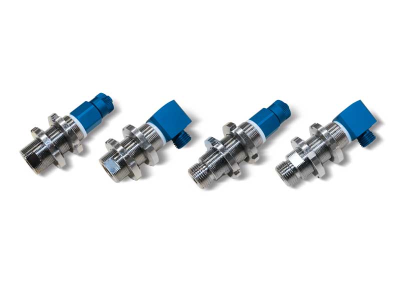
Mini vacuum cup holders with male and female threaded connectors
The vacuum cup holders shown on this page have a shorter stroke and their special design that allow for further bulk and weight reduction in the overall dimensions and weight of these vacuum cups compared to normal mini vacuum cup holders. They are composed of:
- A brass stem equipped with 1/8” and 1/4” gas threaded connections for attaching the vacuum cup;
- A threaded sleeve equipped with nuts, for mounting the vacuum up holder on the automation;
- A spring to cushion the impact of the cup and to, at the same time, maintain constant pressure with the load to be lifted;
- A quick coupling for connection with the suction hose.
Product codes: 200635 200735 201038 201048 201038M 201048M 201058M 208025B 208025
- Physical characteristics: Robust ABS housing, compact and lightweight; mountable on machinery and near the point of use.
- Precision and display: Calibrated and temperature-compensated; integrated display shows values, making an external vacuum gauge unnecessary.
- Signal indication: Two LEDs indicate the status of the two independent digital output signals.
- Programming: Switching points and hysteresis (0–100% of set value) programmable via buttons. Also configurable: threshold comparison, NO/NC contacts, unit selection, parameter lock, and display inversion.
- Display rotation: Free rotation to orient the display without disconnecting pneumatic connections.
- Connections: Pneumatic with double-threaded G 1/8 inch male or
M5 female; electrical M8 4-pin (PUR cable with axial or radial connector available on request).
- Applications: Measurement and control of dry air and non-corrosive gases; ideal for safety signals, cycle start, vacuum suction cup control, and optimizing energy consumption of vacuum generators.
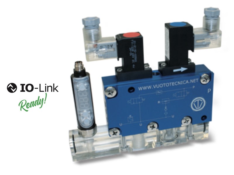
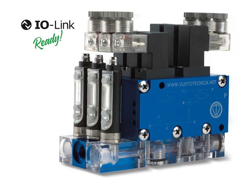
- IO-Link: IO-Link version distinguishable from the standard model by the logo and the “IO-Link” inscription on the housing. Enables bidirectional digital communication, remote parameterization, and advanced diagnostics, turning the sensor into an intelligent device for Industry 4.0.
Product codes: 121010 122511
Multi-function modules with built-in vacuum solenoid valves
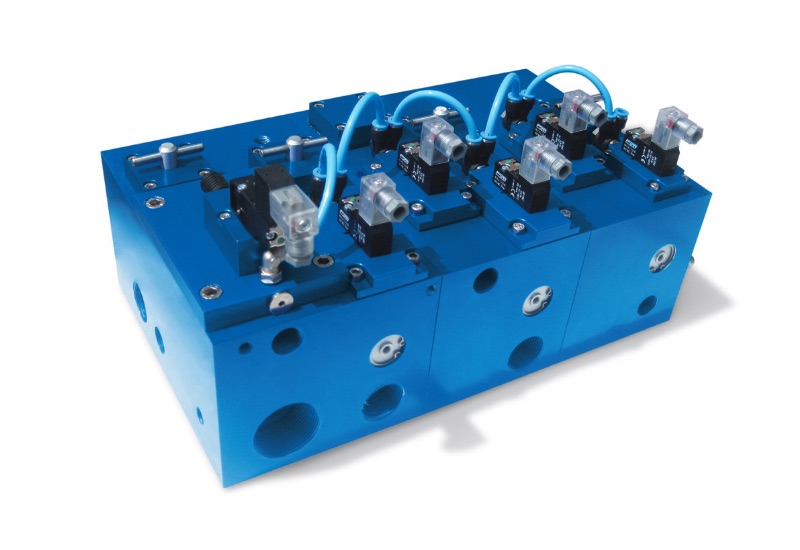
The needs of technical designers in the packaging sector and in the automation sector in general to have more vacuum combined with different functions in the smallest possible space has led us to design and implement this new series of multi-function modules.
Each module has two internal solenoid valves built inside it. Their ducts house the seats for the flow control valves, which can be operated externally by means of special knobs. Various connections made at different points allow for connection of the module to instruments for reading and checking the level of vacuum, such as vacuum gauges, vacuum switches, transducers, etc.
There are three modules currently available:
- Module A: the basic module with two integrated 1”1/2 and 1” solenoid valves, two flow regulators and several additional connections.
- Module B: with two integrated 1/2 "and 1" solenoid valves and two flow regulators. Can be combined with modules A and C.
- Module C: module with two integrated 1/2” solenoid valves, a flow regulator and an additional connection.
Can be combined with module A or B.
The combination of modules A, B and C, feasible using special stainless steel tie-rods, allows for the application of various functions from a single source of vacuum, as well as allowing for the elimination of numerous pipes and fittings, often causing leaks. The multi-function modules are supplied already tested to a guaranteed final level of vacuum of 0.5 mbar and perfectly sealed.
The technical characteristics are those of the pneumatically actuated three-way vacuum solenoid valves:
- Servo-control pressure: 6-7 bar; 4-6 bar for version LP, with non-lubricated compressed air, 5 micron filtration, according to standard ISO 8573-1 class 4
- Operating pressure: from 0.5 to 3000 absolute mbar
- Electric coils: fully plastic-coated in synthetic resin, watertight, insulation class F (up to 155°C) as per standard VDE, with 3 mm two-terminal electrical connections for connectors in compliance with EN 175301-803
- Protection degree IP 54; IP 65 with connector inserted.
- Tolerance permitted on the nominal voltage value: ± 10%
- Electrical power of the coils: from 1 to 2 W, depending on the electrical voltage
- Temperature of suctioned fluid: from – 5 to + 60°C
The ideal use of these multi-function modules is on vacuum thermoformers and vacuum thermo-welders, but they are also widely used on packaging and filling machines in the packaging sector and in all those cases where it is necessary to manage the vacuum at different points and times. Upon request, the modules can be customised and implemented with solenoid valves up to 3” gas. Contact our technical department for further information.
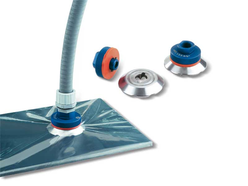
The suction valves described on this page have been designed for a quick vacuum connection on press bags for composite fibre products.
These valves are composed of a steel distributor, to be inserted inside the bag, equipped with a cam housing suitable for the quick coupler for the vacuum connection. The latter is made with reeded and anodised aluminium and is easily coupled with the distributor by simply rotating it on its axis by 90°, once it has been inserted.
A silicone seal, to be placed between the two elements and the press bag, guarantees a perfect vacuum seal. Manual two-way valves, quick couplers or simply flexible pipe fittings can be assembled onto these valves.
They are currently available in the two versions indicated in the table, but can be provided in different sizes and shapes upon request for a minimum amount.
Maximum temperature of use: 220 °C
Product codes: VSS3/8 VSS1/2
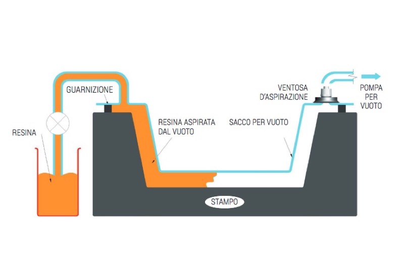
Once laid on the resin infusion mould connections, these suction valves allow a quick vacuum connection and guarantee a perfect seal.
They are made with silicone rubber, while their support is made with anodised aluminium. Manual two-way valves, quick couplers or simply flexible pipe fittings can be assembled onto these valves.
They are available in the two versions shown below, but can be supplied in different sizes and shapes upon request.
Product codes: 088515S1/2 088515S3/4
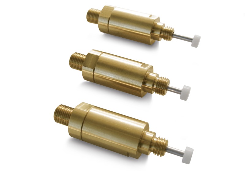
Plunger valves are composed of a natural colour or chrome-plated cylindrical brass body, depending on the items, of a steel plunger with a conical valve, a thrust spring, a nylon disc whose task is to thrust the spring onto a larger contact surface, thus avoiding unsightly prints on the load to be gripped.
Connected to vacuum, they are normally closed.
They activate suction, thus creating a vacuum, only when the plunger is in contact with the gripping surface.
They are also available in various versions, all suitable for our vacuum cups.
Product codes: 190110 190111 190112 190210 190310 190410
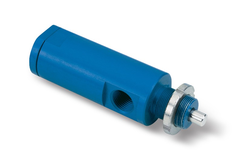
These valves are composed of an anodised aluminium body, a steel pin solidly connected to a conical shutter and of a thrust spring.
Connected to vacuum, they are normally closed.
They activate suction, thus creating vacuum, only when the pin is activated by the cams or any other mechanical device.
They can be used as an alternative to plunger valves when these cannot be assembled onto the vacuum cups.
Product code: 190230
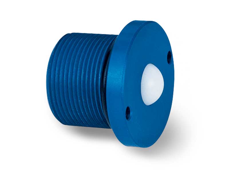
Valves with ball shutters activate suction, creating vacuum in the cups on which they are applied, only when the load to be held activates the sealing shutter.
They are made of an anodised aluminium body, a nylon ball shutter, a calibrated thrust spring and a threaded brass closing plug.
When properly calibrated, they guarantee a perfect vacuum seal.
They are recommended for making vacuum operated clamping surfaces.
They can be supplied in different sizes and shapes upon request and for a minimum quantity to be defined in the order.
Product code: 220110
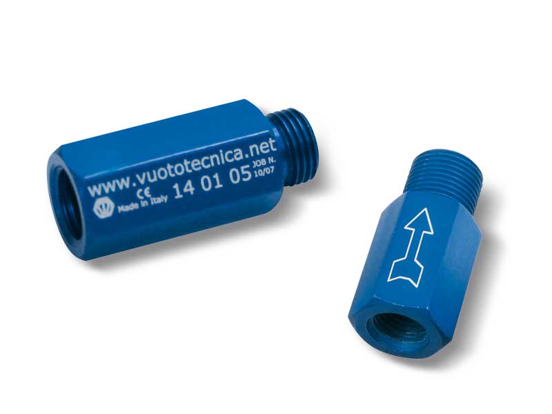
These are special one-way valves that, when properly calibrated, allow a certain quantity of fluid to go through; afterwards, if the fluid continues to go through, they automatically close.
These shut-off valves have been specially designed to be applied on the cups and, in case of lack of objects to be gripped, of defective grips or leaks, they automatically deactivate suction, thus preventing any reduction of the level of vacuum on the other gripping cups.
They are provided calibrated and commissioned, ready to be installed. They are made with anodised aluminium and can be supplied in different shapes and sizes upon request and for a minimum quantity to be defined in the order.
Product codes: 140105 140110 140115 140210 140310 140510 140111 140211 140311
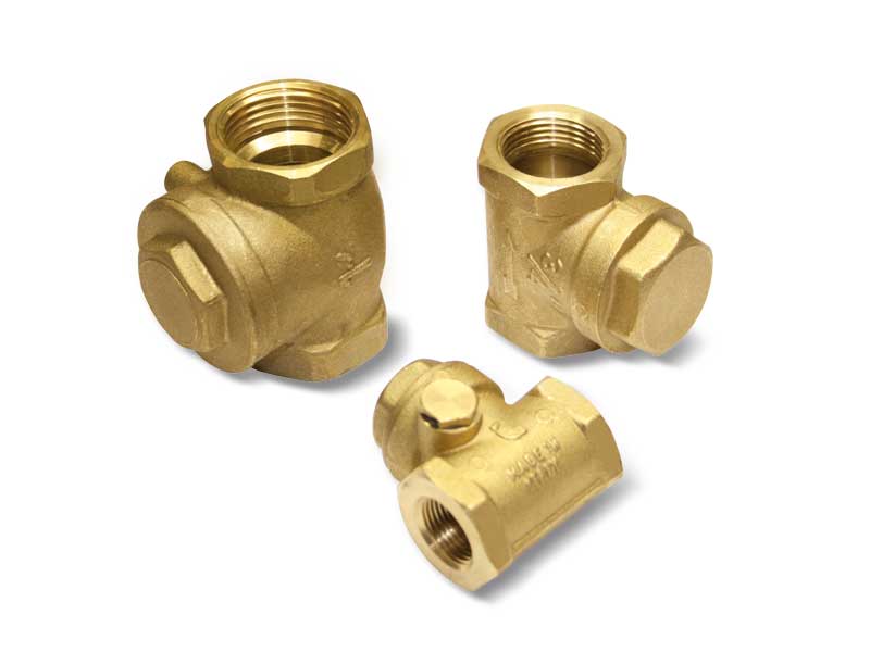
These one-way valves are made with bronze and brass with a seal in NBR nitrile rubber or, upon request, in FKM, only for series 10 ... 11.
To ensure a practical assembly they are available in two versions: horizontal and vertical.
Fitted on the vacuum pump suction inlet, as soon as the latter stop, these valves prevent the air from returning in the plant (piping, tanks, autoclaves, vacuum gripping systems, vacuum cups, etc.), guaranteeing a perfect seal and preventing the oil from returning into the pump stator, which would cause considerable damages.
Therefore, check valves are mandatory on all vacuum pumps with lubrication that do not have them built-in.
Product codes: 100210 100310 100410 100510 100610 100710 100810 100111 100211 100311 100411 100511 100611 100711 100811
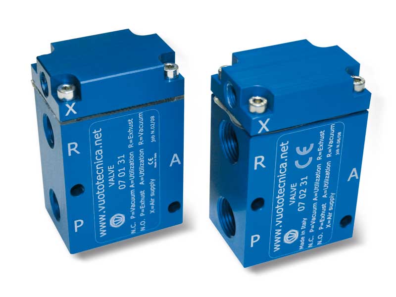
These 2-position, 3-way valves feature pneumatically activated conical shutters.
They can be used normally either closed or open.
They are recommended in all the cases that require a quick exchange between the vacuum pump suction and the air inlet into the circuit for a quick restoration of the atmospheric pressure.
They are composed of an anodised aluminium body, two vulkollan® shutters assembled onto a stainless steel stem, a membrane for servo-control made with special compounds and a thrust spring for the shutter return.
These valves allow reducing frictions and internal dynamic stresses to the minimum. The result being a high response speed and a guarantee of long lasting duration. Technical features
Working pressure: from 0.5 to 3000 mbar abs.
Servo-control pressure: see table
Temperature of the sucked fluid: from -5 to +60 °C
Product codes: 070131 070231 070331 070431 070531 070631 070831 070931
These state of the art solenoid valves feature minimal overall dimensions and high volumetric efficiency and high response speed at any vacuum level.
They are the result of an attentive choice of materials, state of the art constructive techniques and of the in-depth knowledge of our technicians.
This series of solenoid valves is patented.
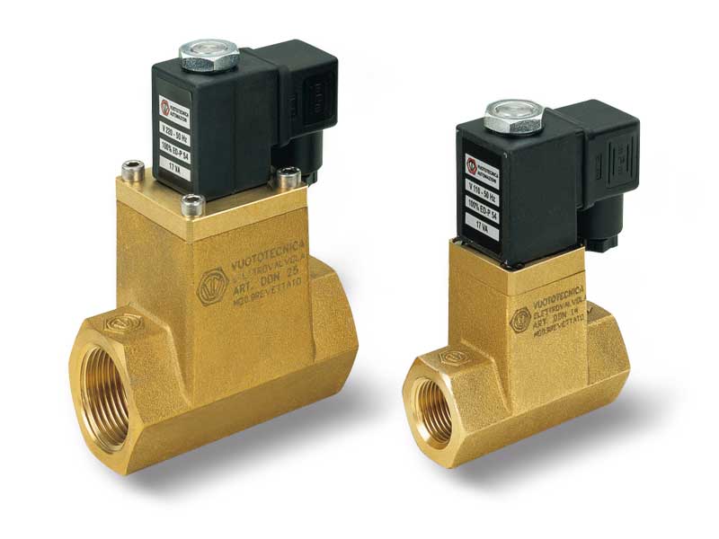
The DDN solenoid valves are direct drive, two-way, two-position valves with direct drive, double shutter and they are normally closed.
They are composed of hot pressed brass body where the connections are located, an internal mechanism with double shutter and of an actuator activated by an electric coil. The standard electric coil is fully plasticised with synthetic resin, tight execution, insulation class F (up to 155 °C) compliant with VDE standards, with 6.3 mm 3-terminal electrical connections in compliance with EN 175301-803 (ex DIN 43650).
Protection degree IP 54; IP 65 with inserted connector.
Allowed tolerance on the voltage nominal value: ±10%.
Max. absorption: 20 V.A. with AC and 18 W with DC (except for DDN 25 which cannot be activated with DC).
The electric coil can be rotated by 360°.
The connector can be rotated by 180° on the coil and can be supplied, upon request, with LED lights, anti-interference circuit and/or with protection devices against overvoltage and polarity reversal.
For proper operation, the installation of the solenoid valve is not recommended upside down.
DDN solenoid valves are particularly indicated for degassers, autoclaves, vacuum thermo-welders and in all applications where suction has to be controlled separately from the air inlet into circuit. Technical features
Working pressure: from 0.5 to 1500 mbar abs.
Temperature of the sucked fluid: from -5 to +60 °C
Product codes: DDN14 DDN25
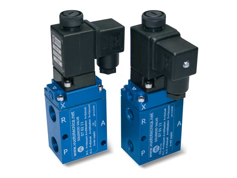
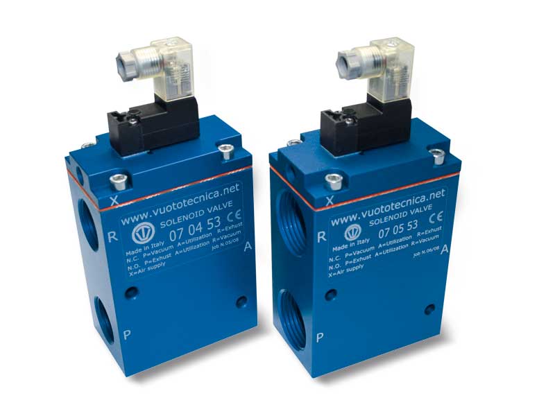
The 3-way vacuum solenoid valves in this series are 2-position valves with pneumatically servo-controlled conical shutters.
They can be used normally either closed or open.
They are composed of an anodised aluminium body, two Vulkollan® shutters assembled onto a stainless steel stem, a membrane for servo-control made with special compounds and a thrust spring for the shutter return; an actuator activated by an electric coil managed the compressed air supply.
These valves allow reducing frictions and internal dynamic stresses to the minimum. The result being a high response speed and a guarantee of long lasting duration. The standard electric coil is fully plasticised with synthetic resin, tight execution, insulation class F (up to 155 °C) compliant with VDE standards, with 6.3 mm 3-terminal electrical connections in compliance with EN 175301-803 (ex DIN 43650).
Protection degree IP 54; IP 65 for inserted connector.
Allowed tolerance on the voltage nominal value: ±10%.
Max. absorption: 20 V.A. in c.a. e 18 W in c.c.
The electric coil can be rotated by 360°.
The connector can be rotated by 180° on the coil and can be supplied, upon request, with Led lights, anti-interference circuit and/or with protection devices against overvoltage and polarity reversal. 3-way vacuum solenoid valves are usually used for intercepting vacuum on feeders and cup stackers, robots, sheet feeders, sack openers and in all those cases where a quick response is needed between suction and the air inlet into the circuit, for a quick restoration of the atmospheric pressure. Technical features
Working pressure: from 0.5 to 3000 mbar abs.
Servo-control pressure: see table
Temperature of the sucked fluid: from -5 to +60 °C
Product codes: 070111 070211 070311 070411 070511 070611 070811 070911
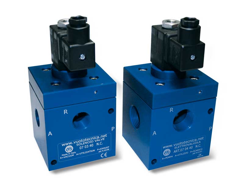
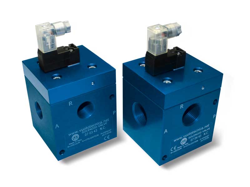
These direct drive three-way, two-position vacuum solenoid valves feature conical shutters servo-controlled by the vacuum.
They are normally closed as standard, but they can be supplied normally open upon request.
They are composed of an anodised aluminium body where the connections are located, two silicone shutters assembled onto a stainless steel stem and a membrane in special reinforced compound. An actuator activated by an electric coil manages the vacuum at the servo-control. The operating principle of these solenoid valves is based on the pressure differential between the vacuum pump or generator and the pressure of the suctioned air.
By addressing this “differential pressure” to the servo-control via the actuator, the shutters can be controlled without compressed air or springs.
Due to their operating principle, they are not recommended on plants with rough vacuum levels (below 850 absolute mbar, equal to 15 % vacuum).
The lack of springs, frictions and internal dynamic stresses favours a high response speed and guarantees long lasting operation.
The standard electric coil is fully plasticised with synthetic resin, tight execution, insulation class F (up to 155°C) compliant with VDE standards, with 6.3 mm three-terminal electrical connections in compliance with EN 175301-803 (ex DIN 43650).
Protection degree IP 54; IP 65 with connector inserted.
Tolerance permitted on the nominal voltage value: ±10%.
Maximum absorption: 20 V.A. with AC and 18 W with DC.
The electric coil can be rotated 360°. The connector can be rotated 180° on the coil and can be supplied, upon request, with LED lights, anti-interference circuit and/or with protection devices against overvoltage and polarity reversal.
The solenoid valves in this series, along with the uses described for the 07 .. 11 series, can be used on plants with no compressed air.
The solenoid valve must be always chosen according to the flow rate and, therefore, to the vacuum pump or generator suction connection. Technical features
Operating pressure: from 0.5 to 850 absolute mbar
Temperature of suctioned fluid: from -5 to +60°C
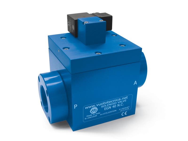
Product codes: 070340NC 070340NO 070440NC 070440NO 070540NC 070540NO 070640NC 070640NO
These direct drive two-way, two-position vacuum solenoid valves in the new series feature a conical shutter servo-controlled by the vacuum.
They are normally closed, but they can be supplied normally open upon request.
They are composed of an anodised aluminium body where the connections are located, a conical silicon shutter assembled onto a stainless steel stem and a membrane in a special rubberised and coated compound. An actuator activated by an electric coil manages the vacuum at the servo-control. The operating principle of these solenoid valves is based on the pressure differential between the vacuum pump or generator and the pressure of the suctioned air. By addressing this “differential pressure” to the servocontrol via the actuator, the shutter can be controlled without compressed air or springs.
Due to their operating principle, they are not recommended on plants with rough vacuum levels (below 850 absolute mbar, equal to 15% vacuum).
The lack of springs, frictions and internal dynamic stresses favours a high response speed and guarantees long lasting operation of the solenoid valve.
The standard electric coil is fully plasticised with synthetic resin, tight execution, insulation class F (up to 155°C) compliant with VDE standards, with 6.3 mm threeterminal electrical connections in compliance with EN 175301-803 (ex-DIN 43650).
Protection degree IP 54, IP 65 with connector inserted.
Tolerance permitted on the nominal voltage value: ± 10%.
Maximum absorption: 20 V.A. with AC and 18 W with DC.
The electric coil can be rotated 360°. The connector can be rotated 180° on the coil and can be supplied, upon request, with LED light, anti-interference circuit and/or with protection devices against overvoltage and polarity reversal.
This series of solenoid valves can be used on vacuum systems without compressed air and in all applications where suction has to be controlled separately from the air inlet into circuit, such as degasifiers, autoclaves, vacuum thermo-welders, etc. The solenoid valve must be always chosen according to the flow rate and, therefore, to the vacuum pump or generator suction connection. Technical features
Operating pressure: from 0.5 to 850 absolute mbar
Temperature of suctioned fluid: from – 5 to + 60°C
Product codes: EGN40NC EGN40NO EGN52NC EGN52NO
Servo-controlled 3-way vacuum solenoid valves with bistable impulse solenoid pilot valve and with low absorption electric coil
These solenoid valves have the same function and the same structure as the previously described three-way valves.
Even their structure is the same; what differentiates them are the bistable impulse solenoid pilot valve powered by a low absorption fitted electrical coil which, with a simple electrical impulse, exchanges the shutter positions and keeps them there even in absence of electricity, until it receives a new impulse of opposite polarity. For this reason, they can only be supplied with direct current electric coils.
Their use is especially recommended in all those cases requiring maximum connection security at the vacuum source, even in the absence of electrical power supply.
The electric coils of the solenoid pilot valve are fully plastic-coated in synthetic resin, watertight, insulation class F (up to 155°C) as per standard VDE, with 3 mm two-terminal electrical connections for connectors in compliance with EN 175301-803(ex DIN 43650) – C. Protection degree IP 54; IP 65 with connector inserted.
Available for voltages 12-24VDC.
Tolerance permitted on the nominal voltage value: ±10%.
Maximum electric power: 1 W
The connector can be rotated 180° on the coil and can be supplied, upon request, with LED lights, anti-interference circuit and/or with protection devices against overvoltage and polarity reversal.
The push-button device for their manual activation cannot be installed on these solenoid valves. Technical features
Operating pressure: from 0.5 to 3000 absolute mbar
Servo-control pressure: see table
Temperature of suctioned fluid: from -5 to +60°C
Product codes: 070153 070253 070353 070453 070553 070653 070853 070953
Direct drive 3-way vacuum solenoid valves with low absorption electric coil
These direct drive three-way, two-position vacuum solenoid valves feature conical shutters servo-controlled by the vacuum.
They are normally closed as standard, but they can be supplied normally open upon request.
They are composed of an anodised aluminium body where the connections are located, two silicone shutters assembled onto a stainless steel stem and a membrane in special reinforced compound. A solenoid pilot valve activated by a built-in electric coil manages the vacuum at the servo-control. The operating principle of these solenoid valves is based on the pressure differential between the vacuum pump or generator and the pressure of the suctioned air. By addressing this “differential pressure” to the servo-control via the solenoid pilot valve, the shutters can be controlled without compressed air or springs.
Due to their operating principle stated above, they are not recommended on plants with rough vacuum levels (below 850 absolute mbar, equal to 15 % vacuum).The lack of springs, frictions and internal dynamic stresses favours a high response speed and guarantees long lasting operation.
The electric coils of the solenoid pilot valve are fully plastic-coated in synthetic resin, watertight, insulation class F (up to 155°C) as per standard VDE, with 3 mm two-terminal electrical connections for connectors in compliance with EN 175301-803 (ex DIN 43650) - C.
Protection degree IP 54; IP 65 with connector inserted.
Available for voltages 12-24V/50-60Hz and 12-24VDC.
Tolerance permitted on the nominal voltage value: ±10%.
Maximum electric power: 2 W
The connector can be rotated 180° on the coil and can be supplied, upon request, with LED lights, anti-interference circuit and/or with protection devices against overvoltage and polarity reversal. A push-button device, built-in the solenoid pilot valve, allows manually opening and closing the solenoid valve.
The solenoid valves in this series, along with the uses described for the 07 .. 11 series, can be used on plants with no compressed air.
The solenoid valve must be always chosen according to the flow rate and, therefore, to the vacuum pump or generator suction connection. Technical features
Operating pressure: from 0.5 to 850 absolute mbar
Temperature of suctioned fluid: from -5 to +60°C
Product codes: 070343NC 070343NO 070443NC 070443NO 070543NC 070543NO
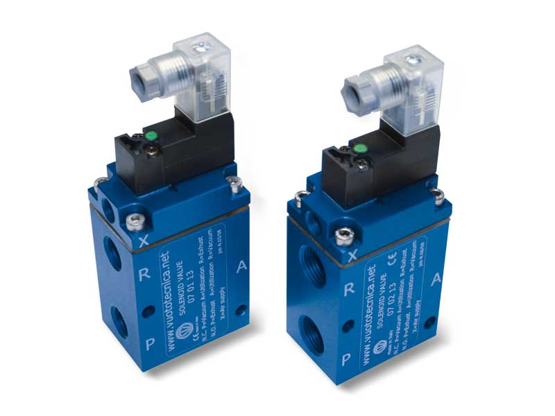
Servo-controlled 3-way vacuum solenoid valves with low absorption electric coil
The three-way vacuum solenoid valves in this series are two-position valves with pneumatically servo-controlled conical shutters.
They can be used normally either closed or open.
They are composed of an anodised aluminium body, two Vulkollan® shutters assembled onto a stainless steel stem, a membrane for servo-control made with special compounds and a thrust spring for the shutter return; a solenoid pilot valve activated by a built-in electric coil managed the compressed air supply.
These valves allow reducing frictions and internal dynamic stresses to the minimum. The result being a high response speed and a guarantee of long lasting duration.
The electric coils of the solenoid pilot valve are fully plastic-coated in synthetic resin, watertight, insulation class F (up to 155°C) as per standard VDE, with 3 mm two-terminal electrical connections for connectors in compliance with EN 175301-803(ex DIN 43650) - C.
Protection degree IP 54; IP 65 with connector inserted.
Available for voltages 12-24V/50-60Hz and 12-24VDC.
Tolerance permitted on the nominal voltage value: ±10%.
Maximum electric power: 2 W
The connector can be rotated 180° on the coil and can be supplied, upon request, with LED lights, anti-interference circuit and/or with protection devices against overvoltage and polarity reversal.
A push-button device, built-in the solenoid pilot valve, allows manually opening and closing the solenoid valve.
The 3-way vacuum solenoid valves are used for vacuum interception on power supply units and suction palletisers, robots, feeders, bag opening units and in all those cases where rapid exchange between pump suction for vacuums and air supply into the circuit is necessary for quick restoration of atmospheric pressure. Technical features
Operating pressure: from 0.5 to 3000 absolute mbar
Servo-control pressure: see table
Temperature of suctioned fluid: from -5 to +60°C
Product codes: 070113 070213 070313 070413 070513 070613 070813 070913
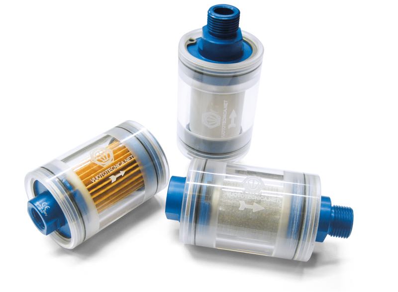
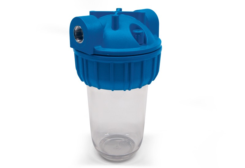
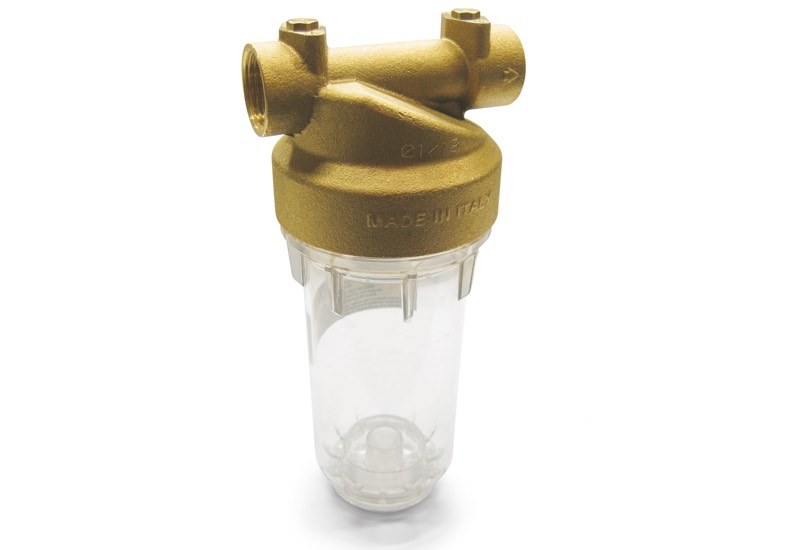
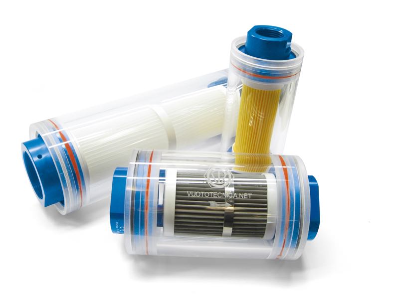
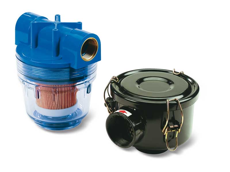
These small in-line filters retain impurities and very fine dust, interfering with the flow rate in a negligible manner. Thanks to their reduced size, they can be directly installed onto vacuum piping, close to the utilities (vacuum cups, vacuum clamping systems, etc.) for a fractionated filtration and a better visual control of all the plant suction points.
They are composed of a cylindrical transparent Plexiglass body closed by two anodised aluminium flanges kept in place by Seeger rings, where all the threaded male or female connections and seals are located. Inside there is a filtering cartridge.
The filters can be inspected by simply removing one of the two flanges. Given the paper filter element, it is not recommended to use these filters (FCL) in the presence of water and oil vapours or condensation. Technical features
Operating pressure: from 0.5 to 3000 absolute mbar
Fluid temperature: from -20 to +60°C
Product codes: FPL1 FCL1 FIL1 FPL2 FCL2 FIL2 FPL3 FCL3 FIL3 FPL1M FCL1M FIL1M FPL2M FCL2M FIL2M FPL3M FCL3M FIL3M FPL1MF FCL1MF FIL1MF FPL2MF FCL2MF FIL2MF FPL3MF FCL3MF FIL3MF
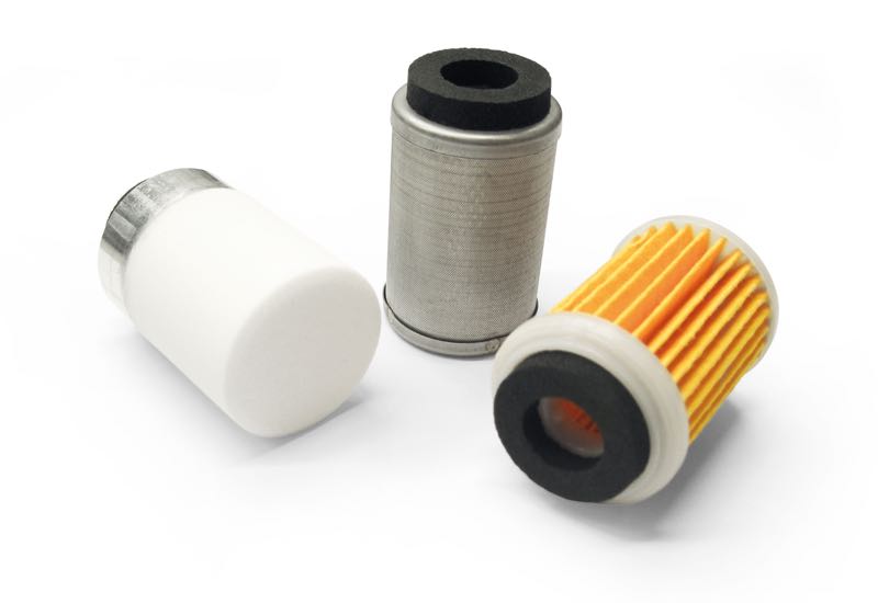
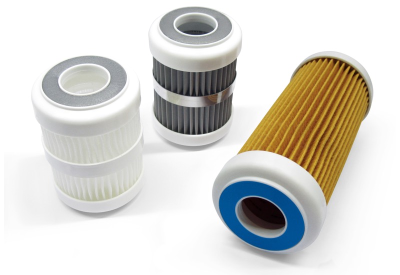
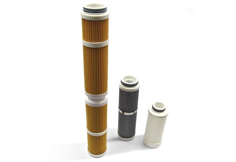
The cartridges illustrated and described below are manufactured from different materials, identified with the following codes:
- 00FCL03 Pleated paper filtering cartridge with compression sealing.
- 00FPL01 Polypropylene mesh filtering cartridge with compression sealing.
- 00FIL01 AISI 304 stainless steel mesh filtering cartridge with compression sealing.
Given the pleated paper filter element, it is not recommended to use these filters in the presence of water and oil vapours or condensation. The filters can be inspected by simply removing one of the two filter flanges.
Product code: 00FCL03 00FPL03 00FIL03
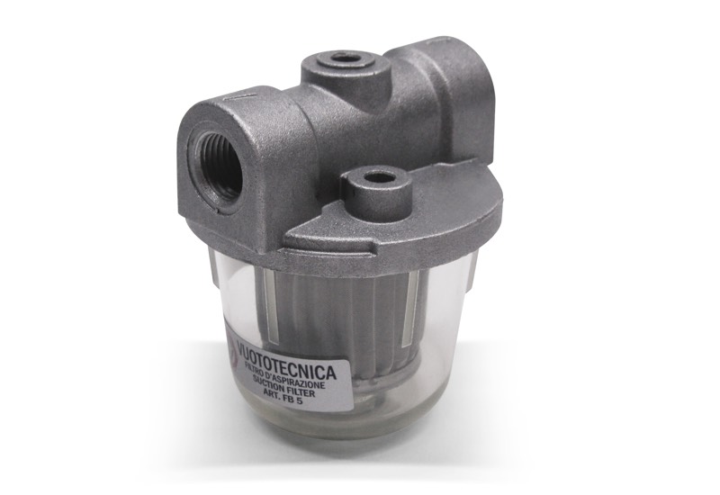
Preventing impurities from reaching the vacuum pump is fundamental to guarantee the correct operation and long duration.
This range of filters, to be placed on the vacuum pump suction inlet or on the plant pipeline, has been designed for this purpose. Their simple and rational structure features threaded connections for the installation and a lid, very easy to open, to allow easily cleaning the filtering cartridge. The lids are made with die-cast aluminium, as are the containers, except for the models FB 5, FB 15 and FB 20 are made of transparent plastic material (cellulose acetate), particularly resistant to impacts.
The end caps are made of electro-galvanized steel, while the standard filter cartridges are made of corrugated stainless-steel mesh, with a filtration rating of 60 μ excluding models FB 28 FB 30, FB 40 and FB 50. Upon specific request and for minimum quantities to be defined at the ordering stage, cartridges with a filtration rating of 100 or 300 μ can be supplied.
The flow rate of these filters ranges from 5 to 300 m3/h. Technical features
Operating pressure: from 0.5 to 3000 absolute mbar
Fluid temperature:
from -20 to +90°C for filters with aluminium container,
from -20 to +50°C for filters with containers in transparent plastic material
Level of filtration: 60 μ - 100 μ
Product codes: FB5 FB15 FB20 FB15A FB20A FB28 FB30 FB40 FB50
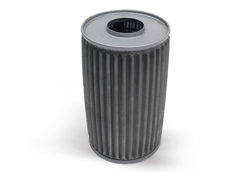
Stainless steel mesh filtering cartridges for FB filters
The cartridges described on this page are suited for FB suction filters.
The standard ones are made with profiled stainless steel mesh with a filtering degree equal to 60 μ.
Note: Cartridges with a filtration rating of 100 or 300 μ can be provided upon specific request and in minimum quantities to be defined in the order.
They are recommended for retaining impurities even in presence of water and oil vapours or condensations, but not for retaining fine and impalpable dust.
Product codes: 00FB03 00FB13 00FB22 00FB34 00FB45 00FB52
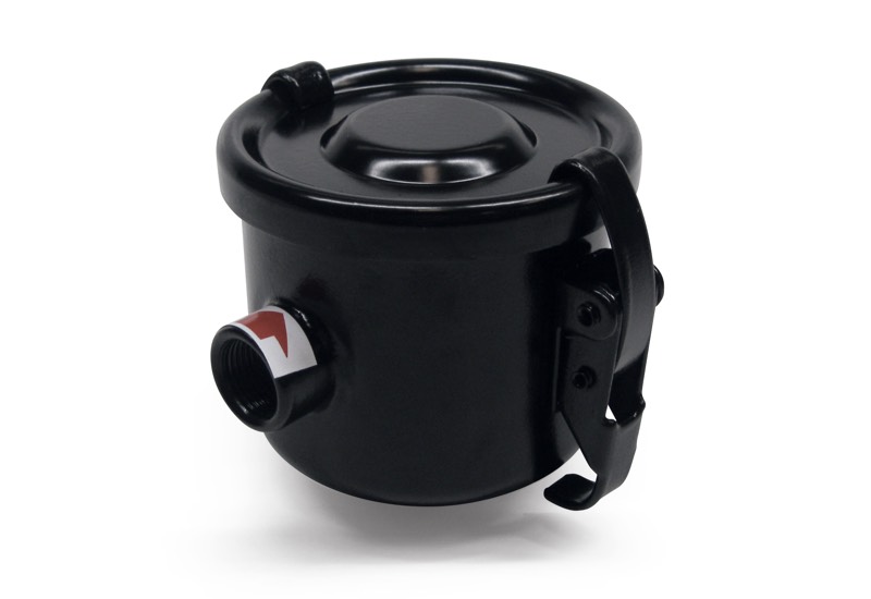
These filters have been designed to allow vacuum pumps to operate even in very dusty environments. Installed onto the pump suction inlet, they are able to retain fine and impalpable dust interfering with the flow rate in a negligible manner.
The filtering cartridge is made with a special treated paper with a filtering degree equal to 5 - 7 μ, which is pleated to increase its surface and is contained in a double perforated sheet steel enclosure. The filtering cartridge container as well as the lid are made with sheet steel and varnished with a special anti-oxidation paint.
A seal located between the lid and the container guarantees a perfect vacuum seal between the two elements. The release clamps applied onto the container allow a quick opening of the lid for the filtering cartridge inspection or replacement.
Due to the paper filtering element, these filters are not recommended in presence of water or oil vapours or condensations. Technical features
Operating pressure: from 0.5 to 2000 absolute mbar
Fluid temperature: from -20 to +60 °C
Level of filtration: 5 - 7 μ
Product codes: FC10 FC20 FC25 FC30 FC35 FC38 FC55 FC40 FC50 FC60 FC80 FC100
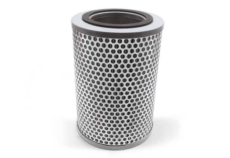
The cartridges described on this page are suited for FC suction filters.
They are made with a special treated paper with a filtering degree equal to 5 - 7 μ, which is pleated to increase its surface and is contained in a double perforated sheet steel enclosure.
They are recommended for retaining fine and impalpable dust, but not in presence of water and oil vapours and condensation.
Product codes: 00FC04 00FC08 00FC15 00FC22 00FC24 00FC33 00FC29 00FC34
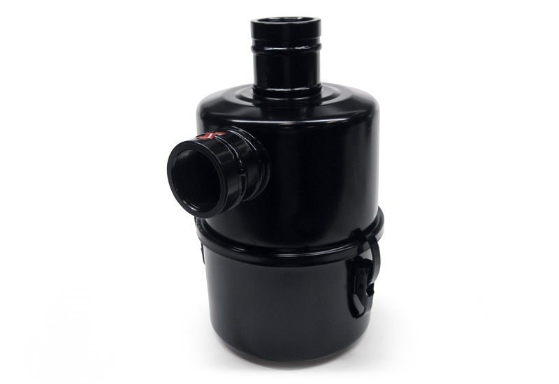
In presence of a considerable amount of fine or impalpable dust, the traditional suction filter would require a cartridge with a filtering degree so high that, along with reducing its operation autonomy, it would also reduce the vacuum pump suction flow rate.
Oil-bath suction filters have been studied in order to overcome this problem.The main feature of these filters is the ability to retain the smallest and most impalpable dust particles, without reducing the vacuum pump suction flow rate.
Oil-bath filters are composed of a sheet steel head and container coupled with an interposed seal and clamped by release clamps.
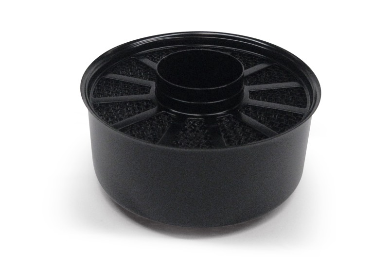
Inside, besides the oil bowl, there are two steel wool filtering cartridges, one of which is detachable and washable, while the other is fixed. The release clamps guarantee easy access for cleaning operations.
They can be used with any kind of oil, even drain oil, as long as it has a minimum viscosity degree. The ideal oil is the same one used for the pump. Oil-bath suction filters are not recommended for dry vacuum pumps.
They are currently available for capacities up to 300 m3/h. Technical features
Operating pressure: from 0.5 to 2000 absolute mbar
Fluid temperature: from -20 to +90 °C
Level of filtration: ≤1 μ
Product codes: FO20 FO30 FO50 FO60
The cartridges described in this page are suited for FO oil-bath suction filters.
They are made with pressed steel wool contained in a double perforated sheet steel enclosure. Their function is to retain fine or impalpable dust impregnated with the filter oil.
Product codes: 00FO04 00FO09 00FO14 00FO19
FO long operation autonomy oil-bath suction filters
In presence of fine or impalpable dust, the traditional suction filter would require a cartridge with a filtering degree so high that, along with reducing its operation autonomy, it would also reduce the vacuum pump suction flow rate.
Oil-bath suction filters have been studied in order to overcome this problem.
The main feature of these filters, in addition to their high autonomy, is their ability to retain the finest suctioned impalpable dusts without reducing the suction flow rate of the pump.
Oil-bath filters are composed of a sheet steel head and container coupled with an interposed seal and clamped by release clamps.Inside, besides the oil bowl, there are two steel wool filtering cartridges, one of which is detachable and washable, while the other is fixed. The release clamps guarantee easy access for cleaning operations.
Two visual indicators allow monitoring of the oil level and the degree of clogging.
They can be used with any kind of oil, even drain oil, as long as it has a minimum viscosity degree. The ideal oil is the same one used for the pump.
Oil-bath suction filters are not recommended for dry vacuum pumps.
They are currently available for 200 and 300 m3/h capacities. Technical features
Operating pressure: from 0.5 to 2000 absolute mbar
Temperature of fluid: from -20 to +90°C
Level of filtration: ≤1 μ
Quantity of oil:
FO 160 - 6.3 L
FO 300 - 12.5 L
Product codes: FO160 FO300
These filters retain impurities and liquids extracted through vacuum cups or vacuum clamping systems, preventing them from entering into the vacuum pumps.
They are composed of:
- A transparent Plexiglas cylindrical container with an extractable lid to allow inspection and cleaning
- A check valve located on the suction inlet for preventing the air from returning in the filter when the pump is idle
- A stainless steel mesh filtering cartridge with a filtering degree equal to 60 μ/100 μ, also located on the suction inlet to retain dust and solid impurities
- A two-way manual valve for service vacuum interception.
- A two-way manual valve for restoring the atmospheric pressure inside the filter
- A radial vacuum gauge the direct reading of the level of vacuum
- A magnetic level switch that stops the pump when the suctioned liquid exceeds the safety level
- A rigid pipe connected to the service to convey the air flow and the sucked liquid to the bottom of the container
- A check valve at the bottom of the filter to automatically drain the sucked liquid and impurities every time the atmospheric pressure is restored inside the filter
- A cock applied on the aforementioned check valve for manual liquid drainage
- A sturdy metal bracket for fixing the filter to the wall. Technical features
Operating pressure: from 0.5 to 1000 absolute mbar
Fluid temperature: from -5 to +50°C
Level of filtration: 60 μ
Product codes: FS5 FS10 FS20 FS25 FS30 FS50
Syphon filter systems with automatic by-pass FS 50 BP and FS 60 BP
The system, composed of two siphon filters, operates initially with suction through filter 1 and with filter 2 excluded. When the suctioned liquid reaches the float on the level switch, automatically by means of the 1” 1/2 three-way vacuum interception solenoid valve for item FS 50 BP and 2” for item FS 60 BP, an exchange is made and suction passes through filter 2.
The input of atmospheric air into filter 1 via the 1/2” three-way solenoid valve installed on its lid, accumulated liquid is allowed to discharge automatically through the check valve with tap on the bottom of the filter. Once liquid has been discharged, after a pre-set time (this operation can be timed), the solenoid valve returns to its initial position, thus allowing recreation of a vacuum inside the filter through a small flexible hose connected to the main vacuum piping.
With this arrangement, there will not be any decrease in the level of vacuum for use when the suction exchange will be carried out between the two filters. This exchange will take place when the liquid reaches the level switch float on filter 2 and, from that moment, the operations described above will be repeated.
The filter system is composed of:
- 2 Plexiglas siphon filters with aluminium lids and complete with accessories, with a flow rate of 38 L each
- 2 1” 1/2 gas three-way servo-operated vacuum solenoid valves, item 07 06 13 for item FS 50 BP and 2” gas servo-operated vacuum solenoid valves, item 07 08 13 for item FS 60 BP
- 2 1/2” gas three-way servo-operated vacuum solenoid valves, item 07 03 13.
- 4 1” 1/2 gas two-way manual valves for vacuum interception, item 13 07 10 for item FS 50 BP and 2” gas for vacuum interception, item 13 08 10 for item FS 60 BP
- 2 Manual 1/2” gas two-way valves, for atmospheric air input, item 13 03 10
- 1 Switchgear enclosed in a special watertight metal box, for single phase electrical voltage Volt 230/ 50 Hz
- 1 Coated profile steel frame to mount all above-described components
The siphon filter system with automatic by-pass is recommended in all those cases in which there is a strong presence of liquid in suction fluids and where machine shut-down for the discharge of liquids suctioned by traditional siphon filters is not allowed. Technical features
Operating pressure: from 0.5 to 2000 absolute mbar
Fluid temperature: from -5 to +50°C
Level of filtration: 100 μ
Product code: FS50BP FS60BP
FP series filtering cartridge containers with compression sealing
The containers of the FP series are suited for the filtering cartridges with compression sealing and are composed of a transparent plastic container and a blue plastic head screwed together with an interposed seal. The number after the item indicates the length in inches of the necessary filtering cartridge.
The cartridge can be chosen in various materials:
pleated paper, pleated polypropylene mesh and stainless steel mesh AISI 304. The following pages describe the filtering cartridges with compression sealing, with all the indications regarding dimensions, materials and filtering degree of each one of them. Technical features
Operating pressure: from 0.5 to 9000 absolute mbar
Temperature of suctioned fluid: from -10 to 45°C
Product codes: FP25/4 FP30/4 FP25/7 FP30/7 NP
The filtering cartridges described in this page, once installed on their container, are able to retain the impurities and dust contained in the sucked fluid, interfering with the vacuum pump or generator capacity in a negligible manner.
They are produced with different materials that can be identified with the following abbreviations:
- Series SP. Pleated paper filtering cartridge with compression sealing.
- Series SS. Pleated polypropylene mesh filtering cartridge with compression sealing.
- Series SA. AISI 304 stainless steel mesh filtering cartridge with compression sealing.
The number after the article indicates the length in inches of the filtering cartridge.
Product codes: SP/4 SP/7 SS/4 SS/7 SA/4 SA/7
FM series quick coupling filtering cartridge containers
The containers of the FM series are suited for quick coupling filtering cartridges and are composed of a transparent SAN (Styrene-acrylic nitrile) container and a head with a reinforced polypropylene ring nut, coupled together with an interposed seal.
The number after the item indicates the length in inches of the necessary filtering cartridge.
The cartridge can be chosen in various materials: pleated paper, pleated polypropylene mesh and AISI 304 stainless steel mesh. The quick coupling filtering cartridges are described on page 5.26, with all the indications regarding dimensions, materials and filtering degree of each one of them. Technical features
Operating pressure: from 0.5 to 9000 absolute mbar
Temperature of suctioned fluid: from -10 to 45°C
Product codes: FM20/7 FM25/7 FM30/7 FM25/10 FM30/10 FM40/10 FM50/10 FM60/10 FM40/20 FM50/20 FM60/20 NF
FK series quick coupling filtering cartridge containers
The containers of the FK series are suited for quick coupling filtering cartridges and are composed of a transparent PET (Polyethylene terephthalate) container and a head with a brass ring nut coupled together with an interposed seal.
The number after the item indicates the length in inches of the necessary filtering cartridge.
The cartridge can be chosen in various materials: pleated paper, pleated polypropylene mesh and AISI 304 stainless steel mesh. The quick coupling filtering cartridges are described on page 5.26, with all the indications regarding dimensions, materials and filtering degree of each one of them. Technical features
Operating pressure: from 0.5 to 9000 absolute mbar
Temperature of suctioned fluid: from -10 to 45°C
Product codes: FK25/7 FK30/7 FK25/10 FK30/10 FK50/10 FK60/10 FK30/20 FK50/20 FK60/20 NK
The filtering cartridges described in this page, once installed on their container, are able to retain the impurities and dust contained in the sucked fluid, interfering with the vacuum pump or generator capacity in a negligible manner.
They are produced with different materials that can be identified with the following abbreviations:
- Series RP. Pleated paper quick coupling filtering cartridge with double O-ring.
- Series RS. Pleated polypropylene mesh quick coupling filtering cartridge with double O-ring.
- Series RA. AISI 304 stainless steel mesh quick coupling filtering cartridge with double O-ring.
The number after the article indicates the length in inches of the filtering cartridge.
Product codes: RP/7 RP/10 RP/10/57 RP/20 RP/20/57 RS/7 RS/10 RS/10/57 RS/20 RS/20/57 RA/7 RA/10 RA/10/57 RA/20 RA/20/57
These large in-line filters retain impurities and very fine dust, interfering with the flow rate in a negligible manner.
They are composed of a cylindrical transparent Plexiglass body closed by two anodised aluminium flanges kept in place by Seeger rings, where all the threaded male or female connections and seals are located; inside there is a filtering cartridge.
The filtering cartridges illustrated and described on this page, installed in their own container, are produced with different materials that can be identified with the following abbreviations:
- Series SP. Pleated paper filtering cartridge with compression sealing.
- Series SS. Pleated polypropylene mesh filtering cartridge with compression sealing.
- Series SA. AISI 304 stainless steel mesh filtering cartridge with compression sealing.
- Series RP. Pleated paper quick coupling filtering cartridge with double O-ring.
- Series RS. Pleated polypropylene mesh quick coupling filtering cartridge with double O-ring.
- Series RA. AISI 304 stainless steel mesh quick coupling filtering cartridge with double O-ring.
Given the paper filter element, it is not recommended to use these filters in the presence of water and oil vapours or condensation.The filters can be inspected by simply removing one of the two flanges. Technical features
Operating pressure: from 0.5 to 3000 absolute mbar
Fluid temperature: from -20 to +60°C
Product codes: FPL4 FCL4 FIL4 FPL5 FCL5 FIL5 FPL6 FCL6 FIL6 FPL7 FCL7 FIL7 SP/5M SS/5M SA/5M RP/5 RS/5 RA/5 RP/10/57 RS/10/57 RA/10/57
Quick coupling fittings, composed of a jack with hose end connector with male threading, guarantee quick and reliable connection.
It is secured by a ball ring with a thrust spring, while a nitrile rubber seal guarantees a perfect vacuum seal. Their design allows free rotation at low speed and quick coupling or uncoupling by means of the knurled nut. As they are not self-retaining, they ensure a full suction passage, optimising the flow rate of the vacuum pumps.
Made entirely of brass, they are available in different sizes to suit various applications.
Product codes: RR3/8 RR1/2 RR3/4 RR1 RR11/4 RR11/2 RRF3/8 RRF1/2 RRF3/4 RRF1 RRF11/2 RRFF3/8 RRFF1/2 RRFF3/4 RRFF1 RRFF11/2
The small pumps described on this page are membrane-type.
They can be used both as vacuum pumps and compressors.
In the latter version they can supply compressed air 100% oil-free up to a maximum 2 bar pressure.
They are composed of:
- An air-cooled single-phase electric motor with protection class IP 00 (assembly execution);
- A pump body made of plastic corrosion-resistant material, complete with fittings at both suction and blowing ports or, upon request, with threaded connections;
- A FKM membrane, fixed to a connecting rod, resistant to wear and corrosion;
- A connecting rod with incorporated long life bearing powered by an eccentric balanced system fitted on the crankshaft;
- An aluminium support, for fastening the pump.
They are available in the versions with single and double head to be used in series or in parallel.
Membrane vacuum mini pumps are very silent (≤ 50dB(A)), they have reduced vibrations and can be installed in any position.
Lubrication-free, they require no maintenance.
Thanks to their minimal overall dimensions and reduced weight, they are particularly indicated for being installed on portable equipment.
They are suited for a discontinuous and non-intense use.
Product codes: H35M H35M11060 H40DM H40DM11060
Working principle
The rotor rotates eccentrically inside a stator and it has grooves in which the vanes move freely and are pushed against the stator inside wall due to the centrifugal force, thus creating as many chambers as the number of vanes. During rotation, the volume of these chambers varies according to their position with respect to the eccentric axis.The chamber volume increase makes the air inside of them expand, thus creating vacuum (suction phase); the volume reduction, on the other hand, generates air compression (exhaust or delivery phase).
The internal design is the same for both rotating compressors and vacuum pumps. We have created two different sucked air conveying principles for our pumps.
These small vacuum pumps have a suction flow rate of 2 and 4 m3/h.
They feature a wick lubrication with oil recirculation, while the rotor, which is cantilevered-fitted on the motor shaft, allows reducing the overall dimensions to the minimum.
The motor and the pump are cooled by the motor fan (surface cooling).
The pumps are equipped with a small tank in line with the pump, which contains the lubrication oil as well as a separator filter to prevent oil mists and to reduce noise.
We strongly recommend installing a check valve and a filter on the suction inlet.Pumps VTL 2 and 4 can also be supplied with single-phase electric motor.
Product codes: VTL2 VTL4
These vacuum pumps have a suction flow rate of 5 and 10 m3.
The vacuum lubrication with oil recirculation can be adjusted via an oiler located in correspondence of the suction inlet.
The rotor is cantilevered-fitted on the motor shaft and, as a result, the overall dimensions are reduced.
The motor and the pump are cooled by the motor fan (surface cooling).
An oil recovery tank is installed on the pump exhaust. This tank contains a separator filter that prevents oil mists and reduces noise.We strongly recommend installing a check valve and a filter on the suction inlet.
Pumps VTL 5 and 10 can also be supplied with a single-phase electric motor.
VTL5 VTL10
These vacuum pumps have a suction flow rate of 25, 30 and 35 m3/h.
The vacuum lubrication with oil recirculation is adjusted via two oilers located in correspondence of the support bearings.
The rotor is cantilevered-fitted on the motor shaft and supported by independent bearings housed in the two pump flanges.
The pump and the electric motor are, therefore, two independent units and fixed onto a special support and connected to each other via an elastic transmission joint.
All this allows using standard electric motors, in the shapes and sizes indicated in the table.
The pump is surface cooled. Heat is dispersed from the outer surface, suitably finned, by means of a radial fan placed between motor and pump.
An oil recovery tank is installed on the pump exhaust. This tank contains a separator filter that prevents oil mists and reduces noise.
We strongly recommend installing a check valve and a filter on the suction inlet.
Also this range of pumps can be supplied with single-phase electric motors.
Product codes: VTL25/FG VTL30/FG VTL35/FG
Vacuum pumps VTLP 25/FG, 30/FG and 35/FG, with disposable lubrication
These vacuum pumps have a suction flow rate of 25, 30 and 35 m3/h.
The vacuum with disposable oil lubrication is adjusted via two oilers located in correspondence of the support bearings.
The rotor is cantilevered-fitted on the motor shaft and supported by independent bearings housed in the two pump flanges.
The pump and the electric motor are, therefore, two independent units and fixed onto a special support and connected to each other via an elastic transmission joint.
All this allows using standard electric motors, in the shapes and sizes indicated in the table.
The pump is surface cooled. Heat is dispersed from the outer surface, suitably finned, by means of a radial fan placed between motor and pump.
An oil recovery tank is installed on the pump exhaust. This tank contains a separator filter that prevents oil mists and reduces noise.
A safety valve is also installed on the tank for the automatic drainage of the exhaust oil when not regularly drained.
The lubrication oil is contained in a special transparent container, fixed to the pump via its support, and controlled by a magnetic level switch.
In pumps with disposable lubrication, the oil is sucked in the pump through an adjustable drip oilers and drained together with the sucked air in the recovery tank, without being put in circulation again. These pumps are necessary when the air to be sucked contains water condensation, solvent vapours or anything else that could affect oil properties.
We strongly recommend installing a check valve and a filter on the suction inlet.
Also this range of pumps can be supplied with single-phase electric motors.
Product codes: VTLP25/FG VTLP30/FG VTLP35/FG
These vacuum pumps have a suction flow rate of 40, 50 and 65 m3/h.
The vacuum lubrication with oil recirculation is adjusted via two oilers located in correspondence of the support bearings.
The rotor is cantilevered-fitted on the motor shaft and supported by independent bearings housed in the two pump flanges.
The pump and the electric motor are, therefore, two independent units and fixed onto a special support and connected to each other via an elastic transmission joint.All this allows using standard electric motors, in the shapes and sizes indicated in the table.
The pump is surface cooled. Heat is dispersed from the outer surface, suitably finned, by means of a radial fan placed between motor and pump.
An oil recovery tank is installed on the pump exhaust. This tank contains a separator filter that prevents oil mists and reduces noise.
A check valve and a filter must be installed on the suction inlet.
These pumps are supplied with three-phase electric motors only.
Product codes: VTL40/G1 VTL50/G1 VTL65/G1
This vacuum pump has a suction flow rate of 105 m3/h.
The vacuum lubrication with oil recirculation is adjusted via two oilers located in correspondence of the support bearings.
The rotor is cantilevered-fitted on the motor shaft and supported by independent bearings housed in the two pump flanges.
The pump and the electric motor are, therefore, two independent units and fixed onto a special support and connected to each other via an elastic transmission joint. All this allows using standard electric motors, in the shapes and sizes indicated in the table.
The pump is surface cooled. Heat is dispersed from the outer surface, suitably finned, by means of a radial fan placed between motor and pump.
An oil recovery tank is installed on the pump exhaust. This tank contains a separator filter that prevents oil mists and reduces noise. A check valve and a filter must be installed on the suction inlet. This pump is supplied with three-phase electric motor only.
Product code: VTL105/G1
Vacuum pumps VTLP 40/G1, 50/G1 and 65/G1, with disposable lubrication
These vacuum pumps have a suction flow rate of 40, 50 and 65 m3/h.
The vacuum with disposable oil lubrication is adjusted via two oilers located in correspondence of the support bearings.
The rotor is cantilevered-fitted on the motor shaft and supported by independent bearings housed in the two pump flanges.
The pump and the electric motor are, therefore, two independent units and fixed onto a special support and connected to each other via an elastic transmission joint.
All this allows using standard electric motors, in the shapes and sizes indicated in the table.
The pump is surface cooled. Heat is dispersed from the outer surface, suitably finned, by means of a radial fan placed between motor and pump.
An oil recovery tank is installed on the pump exhaust. This tank contains a separator filter that prevents oil mists and reduces noise.
A safety valve is also installed on the tank for the automatic drainage of the exhaust oil when not regularly drained.
The lubrication oil is contained in a special transparent container, fixed to the pump via its support, and controlled by a magnetic level switch.
In pumps with disposable lubrication, the oil is sucked in the pump through an adjustable drip oilers and drained together with the sucked air in the recovery tank, without being put in circulation again. These pumps are necessary when the air to be sucked contains water condensation, solvent vapours or anything else that could affect oil properties.A check valve and a filter must be installed on the pump suction inlet.
These pumps are supplied with three-phase electric motors only.
Product codes: VTLP40/G1 VTLP50/G1 VTLP65/G1
Vacuum pump VTLP 105/G1, with disposable lubrication
This vacuum pump has a suction flow rate of 105 m3/h.
The vacuum with disposable oil lubrication is adjusted via two oilers located in correspondence of the support bearings.
The rotor is cantilevered-fitted on the motor shaft and supported by independent bearings housed in the two pump flanges.
The pump and the electric motor are, therefore, two independent units and fixed onto a special support and connected to each other via an elastic transmission joint.
All this allows using standard electric motors, in the shapes and sizes indicated in the table.
The pump is surface cooled. Heat is dispersed from the outer surface, suitably finned, by means of a radial fan placed between motor and pump.
An oil recovery tank is installed on the pump exhaust. This tank contains a separator filter that prevents oil mists and reduces noise.
A safety valve is also installed on the tank for the automatic drainage of the exhaust oil when not regularly drained.
The lubrication oil is contained in a special transparent container, fixed to the pump via its support, and controlled by a magnetic level switch.
In pumps with disposable lubrication, the oil is sucked in the pump through an adjustable drip oilers and drained together with the sucked air in the recovery tank, without being put in circulation again. These pumps are necessary when the air to be sucked contains water condensation, solvent vapours or anything else that could affect oil properties. A check valve and a filter must be installed on the pump suction inlet. This pump is supplied with three-phase electric motor only.
Product code: VTLP105/G1
These small lubrication-free rotary vane vacuum pumps have a suction flow rate of 2 and 4 m3/h. The particular shape of the working chamber and the special graphite, with which the locking flanges and vanes are made, allow these pumps to operate with no lubrication.
The rotor is cantilevered-fitted on the motor shaft, thus reducing overall dimensions to the minimum. The motor and the pump are cooled by the motor fan (surface cooling).
A filter that functions as a silencer is installed on the suction inlet.
We strongly recommend installing a filter on the suction inlet against possible impurities. These pumps are not recommended when the fluid to be sucked contains water or oil vapours or condensations.
Vacuum pumps VTS 2 and 4 can also be supplied with single-phase electric motor.
Product codes: VTS2 VTS4
These lubrication-free rotary vane vacuum pumps have a suction flow rate of 6 and 10 m3/h. The particular shape of the working chamber and the special graphite, with which the locking flanges and vanes are made, allow these pumps to operate with no lubrication.
The rotor is cantilevered-fitted on the motor shaft, thus reducing overall dimensions to the minimum. The motor and the pump are cooled by the motor fan (surface cooling).
A filter that functions as a silencer is installed on the suction inlet.
We strongly recommend installing a filter on the suction inlet against possible impurities. These pumps are not recommended when the fluid to be sucked contains water or oil vapours or condensations.
Vacuum pumps VTS 6 and 10 can also be supplied with single-phase electric motor.
Product codes: VTS6 VTS10
These lubrication-free rotary vane vacuum pumps have a suction flow rate of 10, 15 and 20 m3/h. The particular shape of the working chamber and the special graphite, with which the locking flanges and vanes are made, allow these pumps to operate with no lubrication.
The pump rotor is cantilevered-fitted on the motor shaft and supported by independent bearings housed in the two pump flanges. The pump and the electric motor are, therefore, two independent unitsand fixed onto a special support and connected to each other via an elastic transmission joint.
All this allows using standard electric motors, in the shapes and sizes indicated in the table.
The pump is surface cooled. Heat is dispersed from the outer surface, suitably finned, by means of a radial fan placed between motor and pump.
A filter that functions as a silencer is installed on the suction inlet.
We strongly recommend installing a filter on the suction inlet against possible impurities. These pumps are not recommended when the fluid to be sucked contains water or oil vapours or condensations.
Also this range of pumps can be supplied with single-phase electric motors.
Product codes: VTS10/FG VTS15/FG VTS20/FG
These lubrication-free rotary vane vacuum pumps have a suction flow rate of 25, 30 and 35 m3/h. The particular shape of the working chamber and the special graphite, with which the locking flanges and vanes are made, allow these pumps to operate with no lubrication.
The pump rotor is cantilevered-fitted on the motor shaft and supported by independent bearings housed in the two pump flanges. The pump and the electric motor are, therefore, two independent unitsand fixed onto a special support and connected to each other via an elastic transmission joint.
All this allows using standard electric motors, in the shapes and sizes indicated in the table.
The pump is surface cooled. Heat is dispersed from the outer surface, suitably finned, by means of a radial fan placed between motor and pump.
A filter that functions as a silencer is installed on the suction inlet.
We strongly recommend installing a filter on the suction inlet against possible impurities. These pumps are not recommended when the fluid to be sucked contains water or oil vapours or condensations.
Also this range of pumps can be supplied with single-phase electric motors.
Product codes: VTS25/FG VTS30/FG VTS35/FG
As a standard, these pump sets are built with various capacities and they are composed of:
- A horizontal welded sheet steel tank with perfect vacuum seal.
- A rotary vane vacuum pump to be selected according to the required suctionflow rate and level of vacuum.
- A digital vacuum switch for adjusting the level of vacuum within which to operate.
- A vacuum gauge for a direct reading of the level of vacuum in the tank.
- A switchgear enclosed in a special plastic casing for tanks from 25 to 50 litresand in a watertight metal casing for tanks of 100 litres upwards.
- A manual valve for vacuum interception.
- A cock for condensation drainage.
The level of vacuum, preset via the digital vacuum switch is automatically maintained in the tank.
The pump operation can be both continuous or automatic.
Pump sets are normally used for handling particularly heavy or valuable loads since, in case of electricity failure, they allow the vacuum cups to maintain the grip for a certain amount of time, according to the tank capacity.
These pump sets are recommended for multi-point applications, to centralise vacuum.
These pump sets offer many advantages in energy consumption, since the pump operates only when required by the machine.
Safety pump sets have been designed to centralise vacuum in all work environments such as hospitals, laboratories, etc. where vacuum must be guaranteed 24/7.
They are essentially composed of:
- A horizontal welded sheet steel tank with perfect vacuum seal;
- Two rotary vane vacuum pumps to be selected according to the required suction flow rate and level of vacuum;
- A vacuum gauge for a direct reading of the level of vacuum in the tank;
- Two manual valves for vacuum interception, located between the pumps and the tank and one installed on the tank, for the exclusion or connection of the pump set on a user system;
- A cock for condensation drainage;
- A switchgear enclosed in a special watertight metal casing with switches for automatic or manual pump operation, an alarm device with sound and light signal, alarm-test buttons and hour-counter for counting the hours of actual operation of every single pump.
These safety pump sets normally provide for the operation of one pump with subsequent automatic insertion of the second one for larger consumptions and when, for whatever reason, the plant level of vacuum goes under the preset value.
The automatic timed inverter, located on the switchboard, accurately alternates the pump start- up, so that they are both subject to the same mechanical wear.
The switchboard and remote alarm systems operate when the plant level of vacuum is below the set safety value.
As a standard, these pump sets are built with various capacities and they are composed of:
- A vertical welded sheet steel tank with perfect vacuum seal.
- A rotating vane vacuum pump to be selected according to the required suction capacity and vacuum degree.
- A vacuum switch for adjusting the vacuum level within which to operate.
- A vacuum gauge for a direct reading of the vacuum level in the tank.
- A switchgear enclosed in a special watertight metal casing.
- A manual valve for vacuum interception.
- A cock for condensation drainage.
The level of vacuum, preset via the mini vacuum switch is automatically maintained in the tank. The pump operation can be both continuous or automatic.
The level of vacuum, preset via the mini vacuum switch is automatically maintained in the tank. The pump operation can be both continuous or automatic. These pump sets are normally used for interconnecting several vacuum-operated machines and, for safety reasons, for vacuum handlers since, in case of electricity failure, they allow the vacuum cups to maintain the grip for an amount of time proportional to the tank capacity.
As for energy consumption, in both cases these pump sets offer many advantages, since the pump operates only to restore vacuum in the tank within the preset values and its interventions depend exclusively on the quantity of air that is actually sucked at the service.
Safety pump sets have been designed to centralise vacuum in all work environments such as hospitals, laboratories, etc. where vacuum must be guaranteed 24/7.
They are essentially composed of:
- A vertical welded sheet steel tank with perfect vacuum seal.
- Two rotary vane vacuum pumps to be selected according to the required suctionflow rate and level of vacuum.
- A vacuum gauge for a direct reading of the level of vacuum in the tank.
- Two manual valves for vacuum interception, located between the pumps and the tank and one installed on the tank, for the exclusion or connection of the pump set on a user system.
- A cock for condensation drainage.
- A switchgear enclosed in a special watertight metal casing with switches for automatic or manual pump operation, an alarm device with sound and light signal, alarm-test buttons and hour-counter for counting the hours of actual operation of every single pump.
These safety pump sets normally provide for the operation of one pump with subsequent automatic insertion of the second one for larger consumptions and when, for whatever reason, the plant level of vacuum goes under the preset value.
The automatic timed inverter, located on the switchboard, accurately alternates the pump start-up, so that they are both subject to the same mechanical wear.
The switchboard and remote alarm systems operate when the plant level of vacuum is below the set safety value.
These vacuum pumps have a suction flow rate of 10, 15 and 20 m3/h. The vacuum lubrication with oil recirculation is adjusted via two oilers located in correspondence of the support bearings.
The rotor is cantilevered-fitted on the motor shaft and supported by independent bearings housed in the two pump flanges.
The pump and the electric motor are, therefore, two independent units and fixed onto a special support and connected to each other via an elastic transmission joint.
All this allows using standard electric motors, in the shapes and sizes indicated in the table.
The pump is surface cooled. Heat is dispersed from the outer surface, suitably finned, by means of a radial fan placed between motor and pump.
An oil recovery tank is installed on the pump exhaust. This tank contains a separator filter that prevents oil mists and reduces noise. We strongly recommend installing a check valve and a filter on the suction inlet.
Also this range of pumps can be supplied with single-phase electric motors.
Product codes: VTL10/FG VTL15/FG VTL20/FG
Lubrificated rotary vane vacuum pumps, RVP series - general description
The pumps in this new series are single-stage, rotary vane and with oil-bath lubrication
with recycling. The implementation of cutting edge construction techniques and the use of hi-tech, latest generation materials has allowed for the achievement of high standards of quality, performance, duration and low cost of use. The resulting technical features include:
- High pumping speed in the field of absolute pressure between 850 and 0.5 mbar
- Extremely low noise output
- Low operating temperatures
- No pollution
- Low maintenance
The pumps are driven by an electric motor, coupled by means of an elastic transmission joint (not including RVP 15), in compliance with IEC International Standard 60034 requirements for rotating machines and European Directives for Low Voltage 2014/35/UE, for Electromagnetic Compatibility (EMC) 2014/30/UE, for the limitation of use of hazardous substances RoHS 2011/65/CE and Machine Directive 2006/42/EC for CE marking.
With the exception of electric motors with power lower than 0.75 KW, the efficiency class corresponds to IE3 = Premium Efficiency, with protection degree IP 55, Tolerance of nominal Voltage ± 10% and Class of Insulation F.
A centrifuge fan fitted on the pump shaft ensures a suitable air flow for optimal pump body and radiator cooling (forced surface cooling).
A capacious oil recovery tank located on the pump outlet and equipped with microfibre deoiling cartridges has the function of smoke filtering system and silencer. A special built-in ball cock valve allows for the recovery of oil retained by cartridges. The oil filter, except mod. RVP 15 and 21 pumps, are installed as standard on all.
The oil contained in the system lubricates, cools and seals rotating and fixed pump parts. The check valve on the suction line is an integral part of the pump and is standard while a filter suitable for trapping any suctioned impurities can be supplied upon request.
All pumps except mod. RVP 15 and RVP 21, are supplied standard with a gas ballast valve, which permits high water vapour compatibility. Instead, for mod. RVP 21, the ballast valve can only be installed upon request.
The above described product devices combined with strong, compact construction make RVP series vacuum pumps especially suitable for continuous and heavy-duty use.
Vacuum pumps VTLP 10/FG, 15/FG and 20/FG, with disposable lubrication
These vacuum pumps have a suction flow rate of 10, 15 and 20 m3/h.
The vacuum with disposable oil lubrication is adjusted via two oilers located in correspondence of the support bearings.
The rotor is cantilevered-fitted on the motor shaft and supported by independent bearings housed in the two pump flanges.
The pump and the electric motor are, therefore, two independent units and fixed onto a special support and connected to each other via an elastic transmission joint.
All this allows using standard electric motors, in the shapes and sizes indicated in the table. The pump is surface cooled. Heat is dispersed from the outer surface, suitably finned, by means of a radial fan placed between motor and pump.
An oil recovery tank is installed on the pump exhaust. This tank contains a separator filter that prevents oil mists and reduces noise.
A safety valve is also installed on the tank for the automatic drainage of the exhaust oil when not regularly drained.
The lubrication oil is contained in a special transparent container, fixed to the pump via its support, and controlled by a magnetic level switch.
In pumps with disposable lubrication, the oil is sucked in the pump through an adjustable drip oilers and drained together with the sucked air in the recovery tank, without being put in circulation again. These pumps are necessary when the air to be sucked contains water condensation, solvent vapours or anything else that could affect oil properties.
We strongly recommend installing a check valve and a filter on the suction inlet.
Also this range of pumps can be supplied with single-phase electric motors.
Product codes: VTLP10/FG VTLP15/FG VTLP20/FG
Single-stage vacuum generators with ejector 15 02 10, 15 02 10 LP and 15 02 15 LP
This single-stage vacuum generator operation is based on the Venturi principle. When the generator is supplied with compressed air in P, the vacuum will be generated at connection U and the supply air with the suctioned air will be discharged in R. During the operating cycle, a chamber inside the generator body will be supplied and, when supply stops in P, the compressed air accumulated in it will be discharged through the U connection, quickly the restoring atmospheric pressure of use.
If when using U, for example, it is connected to a vacuum cup, it will disconnect much faster with this ejector system with respect to the previously described vacuum generators. The optimal air supply pressure is normally 6 bar, but for generators with the letters LP in their item, a pressure lower than 4 bar is sufficient to obtain the best performance. They are fully made with anodised aluminium, with brass or aluminium ejectors, depending on the items.
Product codes: 150210 150210LP 150215LP
This new range of vacuum generators also makes use of the Venturi principle.
Their distinctive feature compared with traditional vacuum generators are the two air and vacuum supply connections located in-line on the same axis, while the exhaust connection of the sucked and exhaust air is orthogonal to them and is located on the generator circumference. These vacuum generators are easy to disassemble, thus allowing visibility and access to all the components. The advantages of these generators include reduced overall dimensions, easy maintenance and easy assembly to the vacuum cup supports or to the vacuum cup holders.
As a standard, they are equipped with pressed stainless steel suction filter and a special microfibre silencer, which is wrapped around the exhaust connection, making them particularly silent. They are fully made with anodised aluminium.
Product code: PVP1
Vacuum generators PVP ... SX/SXLP, operate making use of the previously described Venturi principle.
A special new generation silencer installed on them makes them very silent and, thanks to its shape, prevents them from becoming clogged, also allowing the suction of saturated fluids of water condensates or oils, mixed with fine or impalpable powders.
They are supplied as standard with a vacuum gauge for reading the level of vacuum. An additional connection on the body of the generator allows the installation of a vacuum switch for signalling the level of vacuum, or of a pneumatic solenoid valve for a quick restoration of the atmospheric pressure of use. They are fully made with anodised aluminium, with stainless steel ejectors and screws.
These vacuum generators can be used for connecting one or more vacuum cups or equipment with flow rate requirements within the shown values and can operate in particularly dusty or damp environments. Available with suction rates between 8.3 and 18 m3/h and supply pressure 4-6 bar, for items SX and 1-3 bar for items SXLP.
Product codes: PVP7SX PVP14SX PVP18SX PVP7SXLP PVP14SXLP PVP18SXLP
Multi-stage vacuum generators - General description
Our multi-stage vacuum generators produce a maximum vacuum of 90%, equal to a final vacuum level of 100 mbar abs., with different suction capacities. They operate by use of compressed air from 1 to 6 bar. Working principle
Each ejector is based on the Venturi principle: the supply fluid (compressed air) is led high speed by a convergent pipe into the fluid to be extracted (volume of the air to be sucked). This mixture is then led into two or three divergent pipes, where its kinetic energy is transformed into pressure energy for it to enter in the environment at a higher pressure (atmospheric pressure at the exhaust). Technical features
The main asset of multi-stage vacuum generators is its ability to exploit the kinetic energy of the supply compressed air via several specially dimensioned in-line ejectors, before releasing it in the atmosphere. This system allows, given the same capacity, a reduced compressed air consumption compared to the single-stage vacuum generators.
The suction flow rate is indirectly proportional to the differential between the pressure of the fluid to be sucked and the external (atmospheric) pressure.
The reduced size and weight make multi-stage vacuum generators compact in relation to their great suction capacity.
The absence of moving parts make them particularly silent and allow them to be used continuously, without developing heat. Being supplied exclusively by compressed air, these vacuum generators are explosion-proof and can be used in work environments with temperatures ranging from -20 to +80 °C.
They are fully made with stainless materials.
Thanks to all these features, a good filtration of the supply and sucked compressed air is sufficient to make these generators are fully maintenance-free.
These new design vacuum generators feature multiple state of the art ejectors assembled onto small modules. One of their distinctive features is their great suction flow rate compared to their reduced size.
With a compressed air supply of 4 - 5 bar, they can produce a maximum vacuum equal to 85% and a suction flow rate of 3.6 - 18 m3/h, according to the number of modules.
The silencer is built-in.
They are fully made with slightly anodised alloys and can be installed in any position. The multi-stage vacuum generators in this range are suited for interconnecting vacuum cup gripping systems and, in particular, in the industrial robotics sector, which requires equipment with excellent working performance, but with weight and size reduced to the minimum.
Product codes: M3 M7
Single-stage and multi-function vacuum generators series MSVE - General description
The vacuum generators of this new series can fully drive a negative pressure gripping system. By means of coaxial shutters, the original compressed air supply system feeds large quantities of air to both the ejectors and the ejection system, thereby ensuring faster gripping and release of the load.
These vacuum generators are equipped with single-stage ejectors, are powered by low pressure (max. 4 bar), and feature an extremely high emptying speed in relation to their suction flow rate. All this allows for increasingly faster high-performance work cycles.
Two micro solenoid valves manage the compressed air supply to the vacuum ejector and adjustable discharge blow off. The intensity and duration of the latter are managed through a screw-type flow regulator. The check valve built into the suction connector maintains the vacuum in the event of a power outage.
A digital vacuum switch, equipped with a display and commutation LED, manages the compressed air supply and provides a signal to start a cycle under safety conditions. An anodised aluminium distributor with vacuum connectors has an integrated suction filter that can be easily inspected.
By activating the compressed air power micro solenoid valve, the generator creates vacuum for use. As soon as the set maximum value is reached, the digital vacuum switch acts on the electric coil of the micro solenoid valve and stops the air supply, reactivating it when the vacuum falls below the minimum level.
Besides maintaining the vacuum level within set safety values (hysteresis), this modulation allows for considerable compressed air savings. A second signal from the vacuum switch (also adjustable and independent with respect to the first) can be used to start the cycle when the vacuum level reached is suitable for use. Once the work cycle is completed, the micro solenoid valve that supplies compressed air to the generator is deactivated while, at the same time, the ejection solenoid valve is activated for quick restoration of the atmospheric pressure upon use.
The MSVE vacuum generators can be installed in any position and are suitable for suction gripping systems, handling metal sheets, glass, marble, ceramics, plastic, cardboard, wood, etc. and, in particular, for the industrial robotics sector, where equipment with excellent performance and limited weight and bulk are increasingly required.
Multi-stage and multi-function vacuum generators series MVG - General description
These generators are true independent vacuum units that can control an entire vacuum gripping system. Their distinctive features are their compact size and great suction flow rate.
They are composed of a mono-block anodised aluminium structure onto which are assembled:
- A modular and silenced multi-stage vacuum generator.
- A micro solenoid valve for supplying compressed air to the generator.
- A micro solenoid valve for blowing the exhaust compressed air.
- An adjustable flow regulator for dosing the exhaust air.
- A unidirectional check valve, located on the suction inlet, for maintaining the vacuum in case of electricity failure.
- A digital vacuum switch provided with display and commutation LEDs, for managing the compressed air supply and for signalling the safety cycle start-up.
- An anodised aluminium manifold provided with vacuum connections and a built-in filter easy to inspect.
By activating the compressed air power micro solenoid valve, the generator creates vacuum for use. As soon as the preset maximum value is reached, the digital vacuum switch acts on the electric coil of the micro solenoid valve and stops the air supply, reactivating it when the vacuum falls below the minimum level.
Besides maintaining the level of vacuum within set safety values (hysteresis), this modulation allows for considerable compressed air savings.
A second signal from the vacuum switch (also adjustable and independent with respect to the first) can be used to start the cycle when the level of vacuum reached is suitable for use. Once the work cycle is completed, the micro solenoid valve that supplies air to the generator is deactivated while, at the same time, the ejection solenoid valve is activated for quick restoration of the atmospheric pressure upon use.
The multi-function MVG vacuum generators can be installed in any position and are suitable for suction gripping systems, handling metal sheets, glass, marble, ceramics, plastic, cardboard, wood, etc. and, in particular, for the industrial robotics sector, where equipment with excellent performance but with limited weight and bulk are increasingly required.
Multi-stage, multi-function and modular vacuum generators, series GVMM – General description
Modular multi-function vacuum generators are true independent vacuum units that offer an entire vacuum control system.
They feature a reduced thickness and weight compared to their suction flow rate and they have been designed to be assembled with screws to one or more intermediate modules MI. The original internal connection system for the compressed air supply allows communication with no need for external manifolds.
This modular system allows increasing the number of independent vacuum units according to the requirements. In fact, you can order a multi-function vacuum generator and the intermediate modules with the desired capacities, already assembled, or you can assemble one or more intermediate modules to the GVMM generator that has already been installed on the machine, without having to make particular modifications. GVMM vacuum generators are composed of an anodised aluminium mono-block with lid, inside of which the silenced multiple ejectors are installed and the vacuum chamber and the compressed air supply connection are contained.
The following are instead installed on the outside:
- A micro solenoid valve for supplying compressed air to the generator.
- A micro solenoid valve for blowing the exhaust compressed air.
- An adjustable flow regulator for dosing the exhaust air.
- A digital vacuum switch provided with display and commutation LEDs, for managing the compressed air supply and for signalling the safety cycle start-up.
- An anodised aluminium or transparent Plexiglass manifold provided with vacuum connections with built-in suction filter, easy to inspect, and a check valve for maintaining the vacuum in case of electricity or compressed air failure.
By activating the compressed air power micro solenoid valve, the generator creates vacuum for use. As soon as the preset maximum value is reached, the digital vacuum switch acts on the electric coil of the micro solenoid valve and stops the air supply, reactivating it when the vacuum falls below the minimum level.Besides maintaining the level of vacuum within set safety values (hysteresis), this modulation allows for considerable compressed air savings.
A second signal from the vacuum switch (also adjustable and independent with respect to the first) can be used to start the cycle when the level of vacuum reached is suitable for use. Once the work cycle is completed, the micro solenoid valve that supplies air to the generator is deactivated while, at the same time, the ejection solenoid valve is activated for quick restoration of the atmospheric pressure upon use.
GVMM multi-function vacuum generators can be installed in any position and are suited for interconnecting vacuum gripping systems for handling sheet steel, glass, marble, ceramic, plastic, cardboard, wood, etc., and, in particular, for the industrial robotics sector which requires equipment with excellent performance and several independent vacuum units for controlling several applications but with reduced size and weight.
Multi-stage, multi-function and modular intermediate vacuum modules series MI - General description
Intermediate modules are non-independent multi-stage and multi-function vacuum generators to be assembled to the generators of the GVMM range.
Their thickness and weight are reduced to the maximum compared to their suction flow rate and they have been designed to be enclosed between the lid and the base of the GVMM vacuum generator and fixed with screws. The internal connections for the compressed air supply allow communication between them and the basic generator, with no need for external manifolds.
This way, each module becomes an independent vacuum unit that can control an entire vacuum system.
They can be ordered in the desired amount and flow rate, either already assembled onto the GVMM multi-function vacuum generator, or separately, to be assembled to the GVMM generator previously installed onto the machine. In this case, we suggest ordering a screw kit suitable for the number of modules to be assembled.
MI intermediate vacuum modules are made up of the same elements that compose GVMM generators, except for the lid. They operate and they are used as the GVMM multi-function vacuum generator onto which they are assembled.
Single-stage and multi-function vacuum generators series AVG – General information
These generators are independent vacuum units capable of driving a vacuum gripping system They have been specially designed for the AUTOMOTIVE sector and they are equipped with single ejectors that, given the same flow rate as the multi-ejector generators, allow for a quicker grip.
They are provided as standard with a built-in pneumatic energy-saving device.
They are composed of an anodised aluminium mono-block structure, inside of which are installed the ejectors, the servo-controlled slide valve for the compressed air supply and are contained the vacuum chambers as well as the various connections.
The following are instead installed on the outside:
- A bistable impulse solenoid valve for controlling the slide valve.
- A solenoid valve for blowing the ejected compressed air.
- A flow regulator for dosing the ejected compressed air.
- Two silencers for removing noise from the ejected air.
- An aluminium manifold provided with vacuum connections with built-in:
• A pneumatic vacuum switch for managing the compressed air supply according to the set level of vacuum (energy saving).
• A check valve for maintaining the vacuum in case of electricity or compressed air failure.
• A suction filter, easy to inspect through the transparent polycarbonate lid.
OPERATION
By providing an electric impulse to the two-position solenoid valve, the compressed air supply slide valve will be activated and vacuum will be created at the application. Once the preset maximum value has been reached, the pneumatic vacuum switch acts on the servo-controlled valve and interrupts the compressed air supply, restoring it when the value returns below the minimum value.
Besides maintaining the level of vacuum within preset safety values, this modulation also allows a considerable saving of compressed air and occurs even in the absence of electricity. Once the work cycle is completed, the power supply solenoid valve is deactivated by means of an electrical pulse while, at the same time, the ejection solenoid valve is activated for quick restoration of the atmospheric pressure of use.
AVG vacuum generators are fitted for the installation of a digital vacuum switch. Also these vacuum generators can be installed in any position.
SECTORS OF USE
AVG vacuum generators are suitable for suction gripping systems, for the handling of metal sheets, glass, marble, ceramics, plastic, cardboard, wood, etc. and, in particular, for the AUTOMOTIVE sector, where equipment with excellent performance and limited size and weight are increasingly required.
This range of multiple ejector vacuum generators offers increased suction flow rate, given the same compressed air consumption, than single-stage models.
Supply pressure goes between 4-6 bar, for items MX and between 1-3 bar, for MXLP. The capacities go from 10.5 to 31 m3/h. They are fully made with anodised aluminium, with stainless steel ejectors and screws. The EPDM seals, the silicone reed valves and the vacuum gauge are provided as standard. They are equipped with additional intake connections for increased points of usage or control tools.
The suctioned air discharge connections are threaded to allow for installation, upon request, of “free-flow” SSX high sound damping silencers.
Product codes: PVP12MX PVP12MXLP
Multi-stage vacuum generators PVP 40 M / MLP ÷ PVP 300 M / MLP
Created to be assembled on OCTOPUS gripping systems, this series of generators is available with suction capacities between 24 and 320 m3/h. The supply pressure goes from 4-6 bar for M items and from 1-3 bar for MLP items. Level of vacuum and flow rate can be adjusted according to the supply air pressure.
Characterised by their new generation of ejectors, boasting an excellent ratio between the quantity of air consumed and that suctioned, benefiting operational consumption. The silencers are built into all generators.
They are fully made with anodised aluminium, with stainless steel ejectors and screws.
EPDM or FKM seals and reed valves upon request.
Low maintenance and simple scheduled filter cleaning.
Product codes: PVP40M PVP70M PVP100M PVP40MLP PVP70MLP PVP100MLP
This line of generators is available with suction rates between 20 and 103 m3/h. The supply pressure goes from 4-6 bar for MDX items and from 1-3 bar for MDXLP items. The maximum level of vacuum is -90 KPa.
Characterised by their new generation of ejectors, boasting an excellent ratio between the quantity of air consumed and that suctioned, benefiting operational consumption. They are fully made with anodised aluminium, with stainless steel ejectors and screws. The tightness seal is made from EPDM, while the reed valves are made as standard and in FKM, upon request. The “free-flow” SSX high sound damping silencers installed as standard on the air exhaust. They are equipped with additional threaded connections for increased points of usage or for the installation of measurement or control tools.
Upon request, can be supplied with a compressed air energy savings kit ES (ENERGY SAVING SYSTEM), composed of a pneumatic vacuum regulator, a pneumatic coaxial shutter supply valve, a check valve and necessary tubing.
Product codes: PPVP25MDX PVP35MDX PVP50MDX PVP25MDXLP PVP35MDXLP PVP50MDXLP
Multi-stage and modular vacuum generators PVP 150 MD / MDLP ÷ 750 MD / MDLP - General description
The special shape of these vacuum generators has allowed obtaining great suction capacities in very limited overall dimensions.
The new design stainless steel ejectors are assembled on modular frames; the overlapping of one or more frames defines the flow rate of the generators. They are supplied with a flow rate ranging from 85 e 900 m3/h and a maximum level of vacuum of -90KPa. The supply pressure goes from 4-6 bar for MD items and from 1-3 bar for MDLP items. Level of vacuum and flow rate can be adjusted according to the supply air pressure. They are fully made with anodised aluminium.
The sealing gaskets and disc valves are EPDM as standard, but can be supplied in FKM upon request. Also upon request, an energy saving kit for the compressed air ES (Energy Saving System) can be supplied. It is composed of a pneumatic coaxial shutter valve for supply of the compressed air, an integrated pneumatic vacuum switch, a reed valve kit for the check system and a flexible tube with quick fitting to monitor and transmit the value of the level of vacuum to the vacuum switch.
Perfectly soundproofed with silencers built into all generators, offering extremely quiet operation.
Working principle
The compressed air supply blown into a ring chamber concentric to the device, flows at a very high speed towards the centre of the main pipe, thus forming a cyclonic effect. The latter creates a vacuum inside the device and leads a great volume of air towards its outlet.
Therefore, a variation of the air supply pressure will modify the level of vacuum and the amount of sucked air.
Features
The special shape of the flow generators and their straight-flow working principle allow for the suctioning and handling of various nature products without interference. Vacuum Jets are in fact suitable for the handling of powders, granulated products, sawdust, corn, metal chips, liquid or dry food products, etc., or for extracting fumes, coolant mists, water or oil condensation, etc.
The absence of moving parts allows them to be used continuously, without developing heat.
They do not require electricity; therefore, they can be used in work environments with hazardous environments where an ignition source would be dangerous.
Available in anodised aluminium and stainless steel.
Thanks to all these features, a good filtration of the compressed air supply will be sufficient to make these devices fully maintenance-free.
Also the construction of this cartridge vacuum generator was necessary in order to meet the demand for ever smaller and more performing devices in the packaging sector.
The compressed air supply pressure is between 1 and 3 bar, while the maximum level of vacuum is -52 KPa, with a flow rate of 2.6 m3/h.
Also the shape of these generators, like the previous ones described, allows for the suction of dust and small processing waste without clogging problems.
They are made of brass as standard, but upon request they can also be supplied in different metals.
Product code: PVR3OT
Mini pneumatic pump sets are small independent vacuum-producing units, exclusively supplied with compressed air, with reduced size.
They are composed of:
- A small welded sheet steel tank
- A shut off valve to intercept compressed air
- A pressure regulator with filter and pressure gauge
- A compressed air vacuum generator
- A pneumatic drive valve for supplying the vacuum generator operated by the vacuum switch
- A pneumatic vacuum switch for adjusting the level of vacuum
- A vacuum gauge for reading the level of vacuum
- A manual valve for vacuum interception
- A suction filter with FC series paper cartridge
- A cock for condensation drainage from the tank
The level of vacuum, preset via the mini vacuum switch is automatically maintained in the tank.Mini pneumatic pump sets are suited for equipping fixed or mobile working units that require vacuum, such as:
- Trolleys with vacuum cups for fixing and transporting glass and crystals.
- Vacuum clamping systems for ski maintenance, marble drilling and processing, for polishing objects in pewter, copper, silver, etc.
- Hoists with vacuum cups for lifting television sets and household appliances in general, for glass installation in door and window frames, for feeding sheet metal into presses, etc.
The mini pneumatic pump sets do not require any electrical current but only compressed air at 4-6 bar pressure. Recommended in working environments where ignition sources could cause a fire hazard.
Product codes: DOP06PVP12MX DOP06PVP25MX DOP10PVP12MX DOP10PVP25MX
Pneumatic pump sets are self-contained vacuum production units, fed exclusively by compressed air.
They are composed of:
- A welded sheet steel tank
- A compressed air vacuum generator of the series PVP ... MDX ES, equipped with an energy saving device
- A vacuum gauge for reading the level of vacuum
- A manual valve for vacuum interception
- A suction filter with FC series paper cartridge
- A pressure regulator with filter and pressure gauge
- A shut off valve to intercept compressed air
- A cock for condensation drainage from the tank
The level of vacuum in the tank, previously set with the vacuum switch in the generator, is automatically maintained. The pneumatic pump sets are normally used to handle particularly heavy or valuable loads, as it allows vacuum cups to maintain grip for a certain period of time (varies according to tank capacity) even during unexpected absence of power. These pump sets are recommended for multi-point applications, to centralise vacuum. In both cases, use of the pump set is especially advantageous under the profile of energy savings as the generator only operates when a vacuum is required by the utility machine.
The pneumatic pump sets do not require any electrical current but only compressed air at 4-6 bar pressure. Recommended in working environments where ignition sources could cause a fire hazard.
Product codes: DOP25PVP25MDX DOP25PVP35MDX
Pneumatic pump sets are self-contained vacuum production units, fed exclusively by compressed air.
They are composed of:
- A welded sheet steel tank
- A compressed air vacuum generator of the series PVP ... MDR ES, equipped with energy saving device
- A vacuum gauge for a direct reading of the level of vacuum in the tank
- A manual valve for vacuum interception
- A suction filter with FC series paper cartridge
- A pressure regulator with filter
- A shut off valve to intercept compressed air
- A cock for condensation drainage from the tank
The level of vacuum in the tank, previously set with the vacuum switch integrated in the pneumatic coaxial shutter supply valve, is fully automatically. The pneumatic pump sets are normally used to handle particularly heavy or valuable loads, as it allows vacuum cups to maintain grip for a certain period of time (varies according to tank capacity) even during unexpected absence of power. They are also recommended for centralising vacuums, for powering multiple utility machines. In both cases, use of the pump set is especially advantageous under the profile of energy savings as the generator only operates when a vacuum is required by the utility machine.
The pneumatic pump sets do not require any electrical energy but only compressed air at 4-6 bar pressure. Recommended in working environments where ignition sources could cause a fire hazard.
Product code: DOP150PVP150MD
The operation of these single-stage vacuum generators is also based on the Venturi principle. It differs from the generators described above for its increased suction flow rate, lower supply air pressure, lower than 4 bar to obtain the best performance, and for the SSX … silencer with high acoustic dampening, installed as standard on the R exhaust connection.
They are also used in the automotive sector to control vacuum cups, for the handling and gripping of only slightly porous objects, sheet, wood panel, marble slab and glass and other similar objects.
They are fully made with anodised aluminium.
Product code: 150508SX 150510SX
These small cartridge vacuum generators can be integrated directly into the gripping elements of packaging machines.
The maximum yield is offered at low compressed air pressures of 2-3 bar, providing levels of vacuums up to -72 KPa and flow rates between 1 and 4 m3/h.
Their particular shape permits the suction of dust or small processing residues, without creating clogging problems.
They are made as standard in anodised aluminium but can also be supplied in stainless steel, upon request.
Product codes: PVR1 PVR4
Conveyor vacuum generator PVR 25 MS, with support for fastening to vacuum cups
The particular shape of this rectilinear flow vacuum generator allows for the supply of vacuum cups, especially in the presence of abundant quantities of dust, liquids, sawdust, of various origins, and shavings, without interference. It can reach a level of vacuum of -70KPa, a suction flow rate of about 10 m3/h, with a supply pressure of 3 bar.
The support it is equipped with allows it to be fixed to flat vacuum cups, starting from Ø 200 mm, while a special adapter, available upon request, allows the generator to be fixed at a distance. A "free-flow" silencer is installed on the intake air exhaust with high sound reduction, equipped with appropriate safety protection to prevent the dispersion of the sucked solid impurities in the work environment.
Also upon request, it is possible to supply a digital micro vacuum switch, item 12 05 11 P, for checking the level of vacuum inside the vacuum cup, and a vacuum gauge item 09 03 15, for direct reading of the level.
A good filtration of the compressed air supply will be sufficient to make these devices fully maintenance-free. Their use is recommended in particular on vacuum cups for gripping marble and granite, bricks, rusty metal sheets, rough wooden boards and anything else with especially dirty gripping surfaces.
Product code: PVR25MS 120511P 090315
OCTOPUS vacuum gripping system - General description
The OCTOPUS system is our answer to the ever increasing requirements of operational flexibility for palletising robots and vacuum gripping systems in general.
In fact, this system allows gripping objects of any shape and nature, provided that they do not have an excessive transpiration, without having to place or change vacuum cups, and even when their surface occupies only 5% of the entire suction plate. The maximum weight of the load to be lifted will obviously be proportional to the gripping surface.
Standard OCTOPUS systems are composed of:
- One or two compressed air-fed vacuum generator as shown in the picture and in the drawing, that has to be ordered separately, since it is not included in the code, with the exception of item SO 15 20 MX.
- An anodised aluminium box, open on one side, with a built-in micro-fine mesh filter in stainless steel that protects the vacuum generator and is very easy to inspect. On the top outside of the box there are one or more connections for possible installation of control devices or solenoid valves for prompt restoration of the atmospheric pressure on its inside.
- A suction plate sealing the box, also made with anodised aluminium, with calibrated holes equidistant from each other and coated with a special perforated foam rubber. This suction plate can thus perfectly adapt to any gripping surface, whether it be smooth, rough or irregular. With the same system, for instance, it is possible to grip and handle cardboard boxes and the wooden pallet that supports it.
These OCTOPUS systems are also available upon request in dimensions and with vacuum tables and vacuum generators other than those indicated in the tables.
The standard OCTOPUS systems represented on this page differ from those previously described by their larger dimensions and the number of vacuum generators that compose them. More precisely:
- Two compressed air-fed vacuum generator as shown in the picture and in the drawing, that have to be ordered separately, since it is not included in the item code.
- An anodised aluminium box, open on one side, with a built-in micro-fine mesh filter in stainless steel that protects the vacuum generator and is very easy to inspect. On the top outside of the box there are one or more connections for possible installation of control devices or solenoid valves for prompt restoration of the atmospheric pressure on its inside.
- A suction plate sealing the box, also made with anodised aluminium, with calibrated holes equidistant from each other and coated with a special perforated foam rubber. This suction plate can thus perfectly adapt to any gripping surface, whether it be smooth, rough or irregular. With the same system, for instance, it is possible to grip and handle tomato jars, paint cans, ceramic tiles, cardboard boxes, etc. and the wooden pallet that supports them.
These OCTOPUS systems are also available upon request in dimensions and with vacuum tables and vacuum generators other than those indicated in the table.
Product codes: SO40100X SO6080X SO60120X SO80100X
Standard suction plates PX and P2X for OCTOPUS systems
The suction plates PX described on this page are installed as standard on all OCTOPUS systems and, therefore, can be supplied as a spare or replacement part.
They are made with anodised aluminium sheets with calibrated holes equidistant from each other and coated with a special perforated foam rubber with two different thicknesses: 15 mm for suction plates of the PX range; 30 mm, for special suction plates of the P2X range.
The foam rubber is also perforated at the calibrated holes, but its holes have a diameter of 10-15 mm. The use of calibrated holes allows for exact calculation of the flow rate of the vacuum generator to be used, to ensure that, even in the presence of losses due to transpiration or even in case of failure to cover the object to be gripped, a minimum sufficient level of vacuum remains for gripping and handling the load.
Their lifting force was calculated considering a level of vacuum of at least -75 Kpa, the total surface of the holes within the foam rubber and a factor of safety 3.
Product codes: PX0712 PX 0808 PX1520 PX2030 PX2040 PX2060 PX3030 PX3040 PX3050 PX4040 PX4060 PX40100 PX6080 PX60120 PX80100 PXDO10 PXDO35 PXDO50 P2X0712 P2X0808 P2X1520 P2X2030 P2X2040 P2X2060 P2X3030 P2X3040 P2X3050 P2X4040 P2X4060 P2X40100 P2X6080 P2X60120 P2X80100 P2XDO10 P2XDO35 P2XDO50
Standard suction plates with shut-off valves PXE and P2XE for OCTOPUS systems
The suction plates described on this page are the same as the previously described PX and P2X, but with the addition of shut-off valves inserted in each hole. In absence of an object to grip or in case of a defective grip of the foam rubber, the shut-off valves automatically close the suction inlet, thus preventing the level of vacuum from decreasing on the other gripping holes.
This feature reduces the vacuum generator flow rate compared to standard OCTOPUS systems, to the benefit of energy savings. Moreover, the particular shape of our shut-off valves allows the use of the gripping surfaces in any position.
Product codes: PXE2030 PXE2040 PXE2060 PXE3030 PXE3040 PXE3050 PXE4040 PXE4060 PXE40100 PXE6080 PXE60120 PXE80100 PXEDO35 PXEDO50 P2XE2030 P2XE2040 P2XE2060 P2XE3030 P2XE3040 P2XE3050 P2XE4040 P2XE4060 P2XE40100 P2XE6080 P2XE60120 P2XE80100 P2XEDO35 P2XEDO50
Special suction plates PY and P2Y for OCTOPUS systems
Compared to the standard ones, when given the same gripping surface, these suction plates develop a greater force (item PY) and can grip even very rough and uneven surfaces (item P2Y).
They are made with anodised aluminium with calibrated holes and coated with special perforated foam rubber, with two different thicknesses upon request.
They are perfectly interchangeable with the standard suction plates.
Their lifting force was calculated considering a level of vacuum of at least -75 Kpa, the total surface of the holes within the foam rubber and a factor of safety 3.
Product codes: PY1520 PY2030 PY2040 PY2060 PY3030 PY3040 PY3050 PY4040 PY4060 PY40100 PY6080 PY60120 PY80100 PYDO35 PYDO50 P2Y1520 P2Y2030 P2Y2040 P2Y2060 P2Y3030 P2Y3040 P2Y3050 P2Y4040 P2Y4060 P2Y40100 P2Y6080 P2Y60120 P2Y80100 P2YDO35 P2YDO50
Special suction plates with shut-off valves PY2E and P2Y2E for OCTOPUS systems
The suction plates described on this page are the same as the previously described PY and P2Y, but with the addition of shut-off valves inserted in each hole. In absence of an object to grip or in case of a defective grip of the foam rubber, the shut-off valves automatically close the suction inlet, thus preventing the level of vacuum from decreasing on the other gripping holes.
This feature reduces the vacuum generator flow rate compared to OCTOPUS systems with calibrated holes, to the benefit of energy savings. Also these plates an be used in any position without altering the operating features.
Product codes: PY2E2030 PY2E2040 PY2E2060 PY2E3030 PY2E3040 PY2E3050 PY2E4040 PY2E4060 PY2E40100 PY2E6080 PY2E60120 PY2E80100 PY2EDO35 PY2EDO50 P2Y2E2030 P2Y2E2040 P2Y2E2060 P2Y2E3030 P2Y2E3040 P2Y2E3050 P2Y2E4040 P2Y2E4060 P2Y2E40100 P2Y2E6080 P2Y2E60120 P2Y2E80100 P2Y2EDO35 P2Y2EDO50
These suction plates provided with vacuum cups have been designed to ensure a better grip on uneven and very flexible surfaces (pasta or candy bags, blister or skin-film packs, thin cardboard boxes, etc.), which are difficult to grip with suction plates coated with foam rubber. We recommend using bellows cups.
Thanks to their great flexibility, they adapt themselves to any gripping surface, following its profiles and movements during the lifting phase, guaranteeing a firm and safe grip. They are made with anodised aluminium, as are the vacuum cup supports screwed onto them, which are 1/8” gas supports for the PV version and 1/4”gas for the P2V version. They are each equipped with a calibrated hole.
The cups are cold assembled onto the supports with no adhesives and can be provided in other compounds. Also these suction plates are perfectly interchangeable with the standard ones.
Their lifting force has been calculated considering a level of vacuum of at least -75 Kpa, the total vacuum cup surface and a safety factor 3.Upon request, they can be provided with different cups, as long as the diameter does not exceed 22 mm for the PV suction plates and 45 mm for the P2V ones.
Product codes: PV1520 PV2030 PV2040 PV2060 PV3030 PV3040 PV3050 PV4040 PV4060 PV40100 PV6080 PV60120 PV80100 PVDO35 PVDO50 P2V1520 P2V2030 P2V2040 P2V2060 P2V3030 P2V3040 P2V3050 P2V4040 P2V4060 P2V40100 P2V6080 P2V60120 P2V80100 P2VDO35 P2VDO50
Vacuum cup suction plates with shut-off valves PVE for OCTOPUS systems
The suction plates described on this page are the same as the previously described PY and P2V, but with the addition of shut-off valves inserted in each vacuum cup support connection.
In absence of an object to grip or in case of a defective grip of the cup, the shut-off valves automatically close the suction inlet, thus preventing the level of vacuum from decreasing on the other gripping vacuum cups.
This feature reduces the vacuum generator flow rate compared to OCTOPUS systems with calibrated holes, to the benefit of energy savings. Also these plates an be used in any position without compromising correct operation.
Product codes: PVE2030 PVE2040 PVE2060 PVE3030 PVE3040 PVE3050 PVE4040 PVE4060 PVE40100 PVE6080 PVE60120 PVE80100 PVEDO35 PVEDO50
Bag gripping suction plates PJ for OCTOPUS systems
These suction plates have been designed to allow gripping paper or plastic bags containing powders, granulated products, bulk products or liquids. These suction plates are associated with OCTOPUS systems that fully exploit their performance.
They are made with anodised aluminium and are provided with a special foam rubber seal.
They are perfectly interchangeable with the OCTOPUS system standard suction plates.
The special shapes of the seal and the face allow reducing bag deformation during gripping, reducing vacuum loss to a minimum and guaranteeing the largest gripping surface possible.
Their lifting force has been calculated considering a level of vacuum of at least -75 Kpa, the total gripping surface enclosed in the seal and a safety factor 3.
Product codes: PJ0712 PJ0808 PJ1520 PJ2030 PJ2040 PJ2060 PJ3040 PJ3050 PJ4060
Standard suction plates PX e P2X for OCTOPUS gripping bars
The suction plates PX described on this page are installed as standard on all OCTOPUS gripping bars and, therefore, can be supplied as a spare or replacement part.
They are made with anodised aluminium sheets with calibrated holes equidistant from each other and coated with a special perforated foam rubber with two different thicknesses: 20 mm for suction plates of the PX range and 30 mm for special plates P2X.
Their lifting force was calculated considering a level of vacuum of at least -75 Kpa, the total surface of the holes within the foam rubber and a factor of safety 3.
Product codes: PX0860 PX0880 PX08100 PX08120 PX1240 PX1260 PX1280 PX12100 PX12120 PX12140 P2X0860 P2X0880 P2X08100 P2X08120 PX1240 P2X1260 P2X1280 P2X12100 P2X12120 PX12140
Vacuum cup suction plates PV for OCTOPUS gripping bars
These suction plates provided with vacuum cups have been designed to ensure a better grip on uneven and very flexible surfaces (pasta or candy bags, blister or skin-film packs, thin cardboard boxes, etc.), which are difficult to grip with suction plates coated with foam rubber.
We recommend using bellows cups. Thanks to their great flexibility, they adapt themselves to any gripping surface, following its profiles and movements during the lifting phase, guaranteeing a firm and safe grip. They are made with anodised aluminium, as are the vacuum cup supports screwed onto them, which are 1/8” gas supports and are each equipped with a calibrated hole.
The cups are cold assembled onto the supports with no adhesives and can be provided in other compounds. Also these suction plates are perfectly interchangeable with the standard ones.
Their lifting force has been calculated considering a level of vacuum of at least -75 Kpa, the total vacuum cup gripping surface and a safety factor 3.
They can be supplied upon request with different vacuum cups, provided that their diameter is no larger than 22 mm.
Product codes: PV0860 PV0880 PV08100 PV08120 PV1240 PV1260 PV1280 PV12100 PV12120 PV12140
Suction plates with shut-off valves PXE and P2XE for OCTOPUS gripping bars
The suction plates described on this page are the same as the previously described PX and P2X, but with the addition of shut-off valves inserted in each hole.
In absence of an object to grip or in case of a defective grip of the foam rubber, the shut-off valves automatically close the suction inlet, thus preventing the level of vacuum from decreasing on the other gripping holes.
This feature reduces the vacuum generator flow rate compared to standard OCTOPUS gripping bars, to the benefit of energy savings.
Moreover, the particular shape of our shut-off valves allows the use of the gripping surfaces in any position.
Product codes: PXE0860 PXE0880 PXE08100 PXE08120 PXE1240 PXE1260 PXE1280 PXE12100 PXE12120 PXE12140 P2XE0860 P2XE0880 P2XE08100 P2XE08120 P2XE1240 P2XE1260 P2XE1280 P2XE12100 P2XE12120 P2XE12140
The OCTOPUS system is a vacuum gripping device equipped with one or more compressed air-fed vacuum generators (included in the item code).
It is composed of:
- Main body in anodised aluminium;
- Anodised aluminium suction plate with evenly spaced calibrated holes and covered with perforated foam rubber, which ensures adaptability to smooth, rough or uneven surfaces;
- A multi-stage vacuum generator with built-in silencer. These OCTOPUS systems are also available upon request in dimensions and with vacuum tables and vacuum generators other than those indicated in the table.
Product codes: SO0808X SO0712X
OCTOPUS gripping system composition and relative identification codes
The OCTOPUS systems described on the following pages are equipped as standard with PX suction plates.
Should you want to replace these plates with others with different features you will have to modify the identification codes as described in this page.
OCTOPUS vacuum gripping bars - General description
These bars have been created to further facilitate the installation of OCTOPUS vacuum gripping systems on palletising robots. They are based on the same operating principle and, in addition to the advantages and technical features of the standard OCTOPUS, are equipped with a grooved support plate to allow quick installation on the machine and easy positioning with respect to the load to be gripped.
They are in fact composed of:
- A slotted anodised aluminium fixing plate for quick installation onto the machine
- One or more compressed air-fed vacuum generators, depending on their size
- A connection equipped with quick coupling for feeding compressed air to the generators
- An anodised aluminium box, open on one side, with two air inlet connections inside at the end of the cycle, for quick restoration of the atmospheric pressure and one for possible installation of a vacuum switch.
- A suction plate sealing the box, also made with anodised aluminium, with calibrated holes equidistant from each other and coated with a special perforated foam rubber. This suction plate can thus perfectly adapt to any gripping surface, whether it be smooth, rough or irregular. With the same bar, for example, it is possible to grip and move wooden joists or metal profiles and the pallet that supports them.
The OCTOPUS gripping bars described so far are the standard bars: they can be supplied upon request with suction plates and with shut-off valves and, to make them even lighter, the aluminium parts can be made of Polizene, a thermoplastic material that decreases the weight by about 40%.
Vacuum cup suction plates with shut-off valves PVE for OCTOPUS gripping bars
The suction plates described on this page are the same as the previously described PY and P2V, but with the addition of shut-off valves inserted in each vacuum cup support connection. In absence of an object to grip or in case of a defective grip of the cup, the shutoff valves automatically close the suction inlet, thus preventing the level of vacuum from decreasing on the other gripping vacuum cups.
This feature reduces the vacuum generator flow rate compared to standard OCTOPUS gripping bars with calibrated holes, to the benefit of energy savings. Their particular shape of our shut-off valves allows the use of the gripping surfaces in any position.
Product codes: PVE0860 PVE0880 PVE08100 PVE08120 PVE1240 PVE1260 PVE1280 PVE12100 PVE12120 PVE12140
Special PH and P2H suction plates for octopus systems for gripping empty cans, tins, jars and vials without lids or caps
The special suction plates illustrated and described on this page can be installed on OCTOPUS systems to replace the PX and P2X plates.
They are made of anodised aluminium sheets with holes equidistant from each other and coated with a special sponge rubber, microperforated at the holes in the aluminium sheet, in two different thicknesses: 15 mm for PH suction plates and 30 mm for P2H plates.
The use of calibrated holes makes it possible to calculate the flow rate of the vacuum generator to be installed on the OCTOPUS SYSTEM, to ensure that, even in the presence of losses due to transpiration or the absence of some objects to be picked up, there is always a minimum vacuum value, sufficient to grip even the few remaining containers.
The use of these suction plates is recommended for gripping and handling empty cans, tins, vials and jars made of various materials and without lids or caps.
The lifting force of the container will be directly proportional to the degree of vacuum generated on the surface of the mouth of the can or vial to be picked up.
Note: These plates are not suitable for picking up empty plastic or glass water and wine bottles.
All flexible containers must be previously vacuum tested to avoid the risk of implosion.
Product codes: PH1520 PH2030 PH2040 PH2060 PH3030 PH3040 PH3050 PH4040 PH4060 PH40100 PH6080 PH60120 PH80100 PH110130 P2H1520 P2H2030 P2H2040 P2H2060 P2H3030 P2H3040 P2H3050 P2H4040 P2H4060 P2H40100 P2H6080 P2H60120 P2H80100 P2H110130
The experience and production capacity of Vuototecnica has originated a division specially dedicated to the graphics and printing sector. A reference entity, ranging from engineering to services, that offers innovative and advantageous technical solutions under every point of view: performance, reliability, duration and operational economy. A significant demonstration of the Graphic Division specialisation is represented by the new range of products among which:
PNEUMATIC SUCTION AND BLOWING PUMPS
This new generation of highly versatile multiple-ejector pumps (multi-stage) are able to suction or blow as needed and represent a real evolution compared to conventional rotary vane pumps. Characterised by their new generation of ejectors, these pumps boast an excellent ratio between the quantity of air consumed and that suctioned (or generated), benefiting operational consumption. Their level of vacuum (or pressure level) and flow rate can be adjusted based simply on the air supply pressure. The state of the art hi-tech materials have considerably reduced the weight allowing them to be installed directly on the machine. The Vuototecnica research centre has focused its attention on noise reduction, with solutions that provide for full soundproofing and no moving parts, thus prolonging duration and eliminating any vibrations. Furthermore, these pumps are based on the Venturi principle which exploits the compressed air kinetic energy via in-line ejectors and, therefore, do not develop heat. The excellent filtration of the compressed air supply and intake air allows the intake of air free from oil, water condensates and impurities from between the sheets of paper to be separated in the working environment, with no pollution. Other assets of this safe and competitive technology include a minimal maintenance, limited to a regular filter cleaning operation, and reliability with no comparison. The pneumatic suction and blowing pumps are described in the following pages.
VACUUM CYLINDERS
By assembling a vacuum cup onto their perforated stem and creating a vacuum, the cup will quickly come into contact with the sheet or the object to be handled and it will automatically lift it, holding it until the vacuum is excluded. Thanks to all these features, this range of cylinders combined with cups are particularly recommended for separating sheets of paper or plastic. Advantages include: high speed operation, automatic compensation of the height of the objects to be lifted, non-rotating stems and extremely easy fixing. These vacuum cylinders are illustrated and described on the following pages.
VACUUM CUPS
These come in a large variety of shapes and sizes, to guarantee a quick and safe grip and they can be provided in anti-abrasion natural para rubber, nitrile or oil-resistant rubber, silicone, FKM, polyurethane and other compounds, according to the requirements.Vacuum cups are described in detail in Chapter 1. This chapter on the other hand will focus on disc cups only.
The assembly of a pressure adjuster equipped with pressure gauge and of an FCL filter on the suction inlet connection of a vacuum generator of the M .. SSX range has allowed creating these small pneumatic suction pumps. Their main features include reduced overall dimensions compared to their technical performance.
The level of vacuum and flow rate can be adjusted according to the supply air pressure.
These pumps are powered with compressed air with a pressure ranging from 1 to 5 bar and they can produce a maximum vacuum of 85% and a suction flow rate between 2 and 18 m3/h, measured at a normal atmospheric pressure of 1013 mbar.
Based on the Venturi principle, they do not develop heat.
An SSX silencer screwed onto the pump exhaust ensures a silent operation. The filter equipped with a microporous cartridge is located on the suction inlet connection and can keep the finest dust and impurities.
Thanks to their static operating principle, maintenance is reduced to only a simple regular cleaning of the filter.
Product codes: PA3 PA7
A state of the art range of ejectors has allowed creating this range of pneumatic suction pumps featuring an excellent ratio between the amount of consumed air and sucked air, as well as the ability to adjust the vacuum level and capacity according to the supply air pressure.
These pumps are supplied by compressed air with a pressure ranging from 1 to 6 bar (g), and they can produce a maximum vacuum of 90% and a suction capacity between 15 and 320 cum/h, measured at a normal atmospheric pressure of 1013 mbar.
When designing these pumps our attention was focused on noise. In fact, they are perfectly soundproofed and there are no moving parts subject to wear and vibrations. All this results in an extremely silent operation.
Moreover, being based on the Venturi principle, they do not develop heat.
As a standard, they are equipped with a filter/pressure reducer unit for the supply air and a filter with microporous cartridge located on the suction inlet connection which can keep the finest dust and impurities.
The excellent compressed air and sucked filtration allows blowing air free from oil vapours, water condensation and impurities in the work environment, causing no pollution.
The use of light alloys for making these pumps has allowed a considerable reduction of their weight thus allowing them to be directly installed onto the machine. Thanks to their static operating principle, maintenance is reduced to a simple regular cleaning of the filters.
Product codes: PA40 PA70 PA100
The assembly of a pressure adjuster equipped with pressure gauge and of an FCL filter on the suction inlet connection of a vacuum generator of the M .. SSX range has allowed creating these small pneumatic suction pumps. Their main features include reduced overall dimensions compared to their technical performance.
The pressure and flow rate can be adjusted according to the supply air pressure.
These pumps are powered with compressed air with a pressure ranging from 1 to 5 bar and can produce a maximum pressure of 0.7 bar and a blowing flow rate between 2.7 and 31 m3/h, measured at a normal atmospheric pressure of 1013 mbar.
Based on the Venturi principle, they do not develop heat.
The filter equipped with microporous cartridge located on the air inlet connection can keep the finest dust and impurities.
Thanks to their static operating principle, maintenance is reduced to only a simple regular cleaning of the filter.
Product codes: PS3 PS7
Small combined pneumatic suction pumps PA and blowing pumps PS
All the small pneumatic suction and blowing pumps previously described can be combined regardless of their suction or blowing flow rate.
Given the enormous number of possible combinations, for space reasons, this catalogue only describes combinations of pumps with the same size.
Product codes: PA3PS3 PA3PS7 PA7PS3 PA7PS7
Combined pneumatic suction pumps PA and blowing pumps PS
All the pneumatic suction and blowing pumps previously described can be combined regardless of their suction or blowing flow rate.Given the enormous number of possible combinations, for space reasons, this catalogue only describes combinations of pumps with the same size.
Product codes: PA40PS40 PA40PS70 PA40PS100 PA70PS40 PA70PS70 PA70PS100 PA100PS40 PA100PS70 PA100PS100
With the suction and blowing system AS, we have tried to provide the printing industry with an answer to most of their requirements regarding the management of paper during the printing process, or rather:
- The concentration of all the necessary pumps and commands on one single piece.
- An increased printing quality thanks to individually controlled pumps.
- An increase of productivity resulting from the configuration and use of individual pumps.
- Reduced machine idle state due to the pneumatic pumps based on the Venturi principle.
- An improvement of the work environment thanks to the noise reduction, absence of heat and the emission of air free of oil vapours, water condensation and impurities between the sheets of paper to be separated and in the work environment.
- Energy saving due to a low compressed air consumption compared to the amount of sucked (or generated) air.
- Maintenance reduced to a regular cleaning of the filters.
The suction and blowing system AS is composed of a metal, easy-to-place cabinet, inside of which the combined pneumatic pumps PA and PS are located with the supply compressed air interception and adjustment valves.
The suction and blowing capacities of the pumps are determined according to the client’s requirements or to technical specifications of the machine manufacturer.
The blowing and suction connectors are located on the sides of the cabinet for the connection to the application, as well as the filters equipped with micro-porous cartridge against fine dust.
The following are installed on the control panel:
- The pneumatic main switch for supply compressed air interception with a pressure gauge for a direct reading of the line pressure.- The pneumatic switches for supply compressed air interception of every single pump.
- The pressure reducers with relative pressure gauges for adjusting the compressed air of every single pump. The vacuum (or pressure) level as well as the pump flow rate can be adjusted according to the supply air pressure.
- Vacuum gauges and pressure gauges for a direct reading of the vacuum and pressure at the application. - Vacuum gauges for controlling the clogging level of the PS pump filters.
All our pneumatic suction and blowing pumps can be combined regardless of their suction and blowing flow rate and can be installed inside the system cabinet. Given the enormous number of possible combinations, this catalogue only describes combinations of pumps with the same size.
Product code: AS4
Pneumatic suction and blowing pump holding supports
The supports described on this page have been designed to allow a quick assembly of the pneumatic suction and blowing pumps and their easy placement on the machine.
They are made with a sturdy, satin-finished, stainless sheet steel and are equipped with anti-slip and anti-vibration rubber feet.
These supports are currently available for single pneumatic pumps and for the combined ones.
Product codes: GRDIV03 GRDIV01 GRDIV02
Pneumatic suction and blowing pump suction filters
To allow the pneumatic suction and blowing pumps to work even in very dusty environments, it is necessary to use these filters that, installed on the suction inlet connection, can keep the finest dust and impurities and affecting the flow rate in a negligible manner.
The filtering cartridges, in fact, are made with a special treated paper with a porosity level of 5 - 7 micron, and pleated to increase the filtering surface.
FCL filters are composed of a transparent Plexiglass cylindrical body inside of which is located the filtering cartridge locked by two anodised aluminium flanges that are kept in place by Seeger rings, inside of which the threaded connectors and the seals are housed. The filters can be inspected by simply removing one of the two flanges. The container of the filtering element FP is made with plastic and it is screwed onto the blue plastic lid; a gasket located between the two elements ensures a perfect seal.
The container of the filtering element FC, as well as its lid, are made with sheet steel and varnished with a special oxidation-resistant treatment. A seal between the lid and the container ensures a perfect vacuum seal, while the release clamps on the container allow a quick opening of the lid to check or replace the filtering cartridge.
Product codes: FCL1MF FCL2MF FP30/4/SP FC38 FC55
The function of these devices is to test the welding sealing in flow-pack, cellophane or food product wrappings.
They are composed of:
- A transparent Plexiglass cylindrical container into which the water is poured and the vacuum is created.
- A mobile transparent Plexiglass lid with, on its lower part, a perforated disc fixed via a pin which is for keeping the flow-pack wrapping submerged in the water, in the container and on its upper part, the instruments for managing and controlling the vacuum.
- A multiple ejector multi-stage vacuum generator.
- A check valve located on the generator suction inlet to prevent the air from returning into the container when the generator is not in operation.
- A sleeve valve for compressed air interception.
- A supply compressed air reducer equipped with pressure gauge.
- A 2-way manual valve for restoring the atmospheric pressure inside the container.
The wrapping submerged in the water in the container tends to inflate because of the pressure differential produced between the air at atmospheric pressure on its inside and the vacuum created in the container. The higher the level of vacuum reached in the bell jar and the greater the thrust that the air contained in the wrapping will exert on the walls and, therefore, on the weldings. Any air leak from the wrapping due to a defecting welding is proved by bubbles that indicate the exact point of the welding that’s leaking. The level of vacuum that can be reached inside the bell jar depends on the pump installed.
The test values are adjustable and can be automatically repeated.
Available in other versions upon request. Technical features
Operating pressure: from 0.5 to 1000 absolute mbar
Fluid temperature: from -5 to +50°C
Level of filtration: 60 μ
Product code: ATP02 ATP03 ATP04 ATP07
Suction units with syphon filter GA FS 5 and GA FS 10
These suction units with syphon filter allow sucking fluids saturated with condensation or mixed with water and liquids. They share all the best technical features of syphon filters and vacuum generators. In fact, they keep liquids and solid impurities, while the vacuum generator can suck fluids saturated with vapours or liquid condensation without compromising its performance.
These devices are composed of:
- A standard syphon filter described in Chapter 5.
- A compressed air-fed multi-stage vacuum generator.
- A pneumatic vacuum switch for adjusting the level of vacuum
- A vacuum gauge for a direct reading of the level of vacuum in the container.
- A pneumatic valve for supplying the vacuum generator operated by the vacuum switch
- A sleeve valve for compressed air interception.
The level of vacuum, preset with the vacuum switch, is automatically maintained in the Plexiglass container. These suction units with syphon filter are suited for vacuum cup clamping systems for gripping glass, marble, granite, light alloys and in all those cases with a considerable presence of refrigerating liquids.
They are also recommended for suctioning creamy or muddy substances which can be difficult to handle with traditional pumps.
These suction assemblies are fed by compressed air at a pressure of 4-6 bar only. Available in other versions upon request. Technical features
Operating pressure: from 0.5 to 1000 absolute mbar
Fluid temperature: from -5 to +50°C
Level of filtration: 60 μ
Product code: GAFS5 GAFS10
Suction units with syphon filter GA FS 20 ES ÷ GA FS 30 ES
These suction units with syphon filters share the same features and functions as the previous ones; their distinctive features are their size and the type of generator installed. Their functions are also the same.
These devices are composed of:
- A standard syphon filter described in Chapter 5.
- A compressed air-operated multi-stage vacuum generator with a built-in energy-saving system ES.
- A vacuum gauge for a direct reading of the level of vacuum in the container.
- A shut off valve to intercept compressed air.
The level of vacuum, preset with the vacuum switch, is automatically maintained in the Plexiglass container. Like the previous ones, these suction units with syphon filter are also suited for vacuum cup clamping systems for gripping glass, marble, granite, light alloys and in all those cases with a considerable presence of refrigerating liquids.
They are also recommended for suctioning creamy or muddy substances which can be difficult to handle with traditional pumps.These suction assemblies are fed by compressed air at a pressure of 4-6 bar only. Available in other versions upon request.
Technical features
Operating pressure: from 0.5 to 1000 absolute mbar
Fluid temperature: from -5 to +50°C
Level of filtration: 60 μ
Product codes: GAFS20ES GAFS25ES GAFS30ES
Samples and equipment for demonstration use - Test bench and tests for the selection of vacuum cups - BT 00
The device, equipped with 6 vacuum and 2 pneumatic sockets, lets users carry out vacuum or Bernoulli suction cups tests on the objects to be gripped or moved, to aid in correctly choosing gripping cups.
This is a useful tool to have at trade show exhibitions, in a showroom or in a test room, for gripping or handling demonstrations or for technical personnel training dedicated to vacuum technology.
The device must be connected to compressed air, vacuum and the electrical power line.
Contact our technical department for further information. Technical features
Electrical power: Single-phase V230 ± 10% 50/60 Hz
Electric power: 0.5 kw
Compressed air consumption: 390 L/min 2bar
Weight: 30 kg
Samples and equipment for demonstration use - Test bench and tests for the selection of vacuum cups - BT01
The device, equipped with 6 vacuum and 2 pneumatic sockets, lets users carry out vacuum or Bernoulli suction cups tests on the objects to be gripped or moved, to aid in correctly choosing gripping cups.
This is a useful tool to have at trade show exhibitions, in a showroom or in a test room, for gripping or handling demonstrations or for technical personnel training dedicated to vacuum technology.
The device is already equipped with its own vacuum generator and only needs to be connected to compressed air and to the electrical power line.
Contact our technical department for further information. Technical features
Electrical power: Single-phase V230 ± 10% 50/60 Hz
Electric power: 1.5 kw
Compressed air consumption: 390 L/min 2bar
BT01 weight: 115 kg
Flight case 01 weight: 200 kg
Total weight: 315 kg
Samples and equipment for demonstration use - Demonstration unit for the handling of powders and granulated products with flow generators CX - CONVY01
The special shape of the flow generators with which this unit is supplied and their straight-flow working principle allow for the suctioning and handling of various nature products without interference.
As previously described, this device is also specially recommended for exhibitions at trade shows, showrooms or test rooms, for practical demonstrations on the handling and transfer of powders, granulated products, sawdust, grains, metal shavings, liquid or dry food products, etc.
Requires connection to compressed air and to the electrical power line. Technical features
Electrical power: Single-phase V230 ± 10% 50/60 Hz
Electric power: 0.5 kw
Compressed air consumption: 390 L/min 2bar
CONVY01 weight: 90 kg
Flight case 01 weight: 200 kg
Total weight: 290 kg